
Seesaw Model
Loading the math board and drawing, please wait…
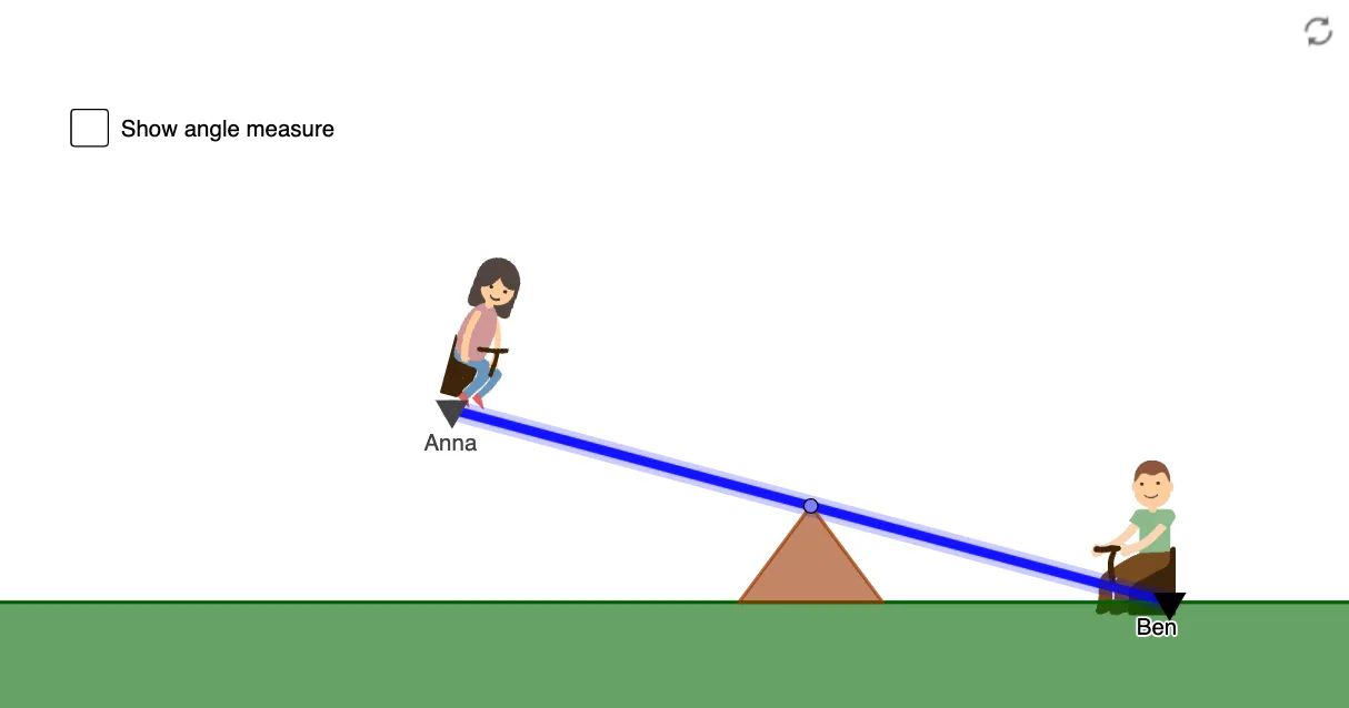
This example dynamically demonstrates the balance principle of a seesaw, visually showcasing the physical application of the lever principle. It involves core mathematical concepts such as geometric construction (points, lines, angles, reflections), ratios, and coordinate geometry. Construction highlights include commands like Intersect, Point, Ray, OrthogonalLine, Mirror, Line, Segment, Polygon, and Angle from the GeoGebra summary. Suitable for middle school and above, it serves as a teaching tool for geometric construction and mathematical modeling of physical principles.
GeoGebra Commands & Parameters
Intersect(xAxis, yAxis) → APoint(yAxis) → BRay(A, B) → fPoint(f) → COrthogonalLine(C, f) → gPoint(xAxis) → DOrthogonalLine(D, g) → hMirror(D, g) → D'OrthogonalLine(D', h) → iMirror(D, f) → D'_1Line(D'_1, h) → jSegment(D', D) → kIntersect(i, j) → ESegment(D'_1, E) → lPoint(l) → seatALine(C, seatA) → mIntersect(g, l) → GIntersect(g, k) → HIntersect(m, k) → AnnaSegment(Anna, seatA) → nIntersect(xAxis, yAxis) → FPoint(xAxis) → JPoint(xAxis) → KPolygon(C, J, K) → t1, k_1, c, j_1Angle(D'_1, C, seatA) → αOrthogonalLine(seatA, n) → pPoint(Circle[seatA, 2]) → NSegment(seatA, N) → qOrthogonalLine(N, yAxis) → rPoint(r) → OPolygon(N, O, 4) → poly1, s, t, d, e, P, QOrthogonalLine(Anna, m) → f_1Point(Circle[Anna, 1.75]) → LSegment(Anna, L) → g_1Line(L, m) → h_1Point(h_1) → RPolygon(R, L, 4) → poly2, i_1, l_1, m_1, n_1, S, T
AI Drawing Prompt Reference
Draw a seesaw model to demonstrate the principle of balance. Start by plotting the x and y axes and identifying the origin. Draw a ray from the origin along the x-axis to the right, and another ray from the origin along the y-axis upwards. With the intersection of the ray and the x-axis as the center, draw a circle to intersect the ray at a point. Connect this point to the intersection of the ray and the x-axis. Repeat this process with the intersection of the ray and the y-axis as the center. Connect these points to form the shape of the seesaw, and label the key points and segments.
The prompt above was compiled from the original drawing commands and is for reference only.