
Sean Jackson Constructions: Geometric Construction with Segments, Circles, and D
Loading the math board and drawing, please wait…
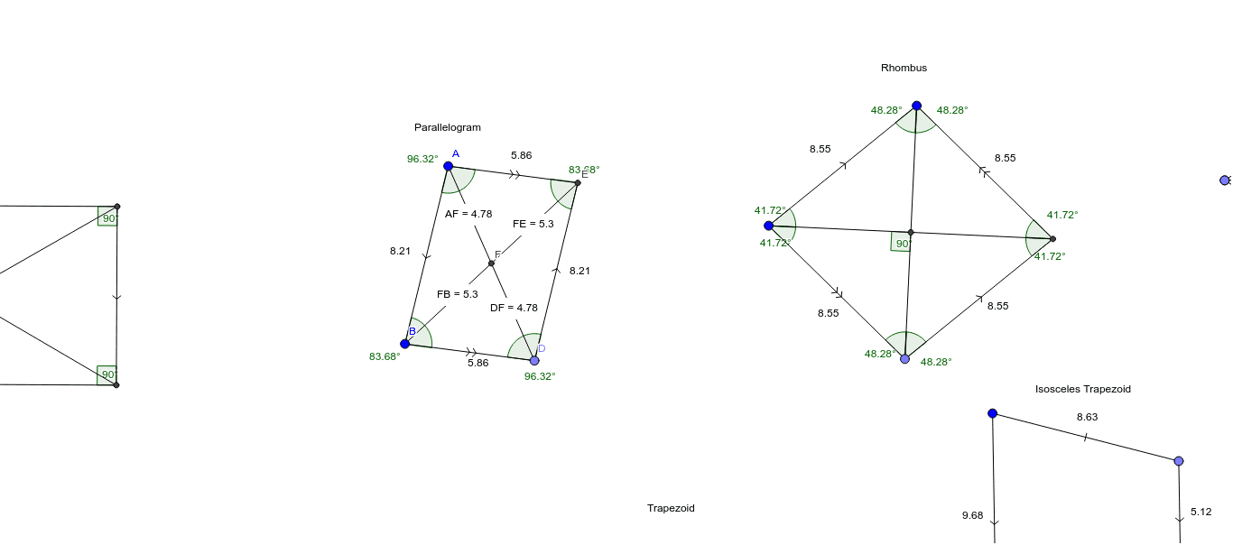
This GeoGebra example demonstrates a series of geometric constructions built from fundamental elements such as points, lines, segments, and circles, showcasing relationships like intersections, perpendicularity, midpoints, and mirror images, along with explicit distance measurements. The core mathematical concepts involve classical geometric construction (ruler-and-compass style), properties of lines and circles, angle relationships, and metric distances. The construction uses GeoGebra commands including Segment, Line, Point, Intersect, Angle, Distance, Circle, OrthogonalLine, Midpoint, and Mirror, creating a rich set of objects: points A, B, C, D, E, F, G, H, I, J, K; segments and lines labeled a, b, c, d, e, f, h, g, i, k, j, q, l, m, n, p, r; angles α, β, γ, δ; and text objects (TextAF, TextFE, TextDF, TextFB) displaying computed distances. This resource is suitable for middle and high school geometry classes, geometric construction practice, and introductory explorations in dynamic mathematics software, helping learners understand how to build and analyze complex figures step by step.
GeoGebra Commands & Parameters
Segment(A, B) → aLine(C, a) → bPoint(b) → DSegment(B, D) → cLine(A, c) → dIntersect(b, d) → ESegment(D, E) → eSegment(A, E) → fAngle(B, A, E) → αAngle(A, E, D) → βAngle(E, D, B) → γAngle(D, B, A) → δSegment(E, B) → hSegment(A, D) → gIntersect(h, g) → FDistance(A, F) → distanceAFDistance(F, E) → distanceFEDistance(D, F) → distanceDFDistance(F, B) → distanceFBSegment(G, H) → iCircle(G, H) → kPoint(k) → JSegment(G, J) → jCircle(G, H) → qLine(J, i) → lLine(H, j) → mIntersect(l, m) → KSegment(J, K) → nSegment(K, H) → pSegment(H, J) → rSegment(G, K) → sIntersect(r, s) → LAngle(G, L, J) → εAngle(K, J, L) → ζAngle(L, J, G) → ηAngle(J, G, L) → θAngle(L, G, H) → ιAngle(G, H, L) → κAngle(L, H, K) → λAngle(H, K, L) → μAngle(L, K, J) → νSegment(M, N) → tLine(O, t) → a_1OrthogonalLine(N, t) → b_1OrthogonalLine(M, t) → c_1Intersect(a_1, c_1) → PIntersect(a_1, b_1) → QSegment(N, Q) → d_1Segment(Q, P) → e_1Segment(P, M) → f_1Angle(M, N, Q) → ξAngle(N, Q, P) → οAngle(Q, P, M) → ρAngle(P, M, N) → σSegment(N, P) → g_1Segment(Q, M) → h_1Segment(R, S) → i_1Circle(R, S) → k_1OrthogonalLine(R, i_1) → j_1Circle(R, S) → p_1Intersect(p_1, j_1, 1) → TLine(T, i_1) → l_1OrthogonalLine(S, i_1) → m_1Intersect(l_1, m_1) → UIntersect(j_1, l_1) → VSegment(V, R) → n_1Segment(U, S) → q_1Segment(V, U) → r_1Segment(R, U) → s_1Segment(S, V) → t_1Intersect(s_1, t_1) → WAngle(U, W, S) → τAngle(S, W, R) → υAngle(R, W, V) → ϕSegment(Z, A_1) → a_2Line(B_1, a_2) → b_2Point(b_2) → C_1Segment(Z, C_1) → c_2Segment(A_1, B_1) → d_2Segment(C_1, B_1) → e_2Midpoint(c_2) → D_1Midpoint(d_2) → E_1Segment(D_1, E_1) → f_2Segment(F_1, G_1) → g_2Line(H_1, g_2) → h_2Point(h_2) → I_1Segment(F_1, I_1) → i_2Midpoint(g_2) → J_1OrthogonalLine(J_1, g_2) → j_2Mirror(F_1, j_2) → K_1Mirror(I_1, j_2) → L_1Segment(K_1, L_1) → k_2Segment(I_1, L_1) → l_2Segment(P_1, Q_1) → p_2Midpoint(p_2) → R_1OrthogonalLine(R_1, p_2) → q_2Point(q_2) → O_1Segment(P_1, O_1) → n_2Mirror(P_1, q_2) → S_1Mirror(O_1, q_2) → T_1Segment(S_1, T_1) → r_2Point(q_2) → U_1Segment(Q_1, U_1) → s_2Mirror(Q_1, q_2) → V_1Mirror(U_1, q_2) → W_1Segment(V_1, W_1) → t_2Segment(O_1, U_1) → a_3Intersect(p_2, a_3) → Z_1Angle(Q_1, Z_1, O_1) → ψAngle(U_1, P_1, O_1) → χAngle(O_1, Q_1, U_1) → α_1Angle(V, R, S) → ωAngle(S, U, V) → β_1Angle(W, V, R) → γ_1Angle(W, S, U) → δ_1
AI Drawing Prompt Reference
Draw a geometric construction: start with a segment, extend a line from one endpoint, pick a point on that line, connect it to the other endpoint, then draw another line through that other endpoint intersecting the first line, forming a triangle with interior angles labeled. Next, connect triangle vertices to midpoints of opposite sides, mark the intersection, and measure distances. Then draw another segment, use it as a radius to make a circle, pick a point on the circle, construct a triangle, and label its angles. Finally, draw a segment, erect perpendiculars at both ends, and draw a line through one endpoint intersecting the perpendiculars, forming a rectangle with intersection points marked.
The prompt above was compiled from the original drawing commands and is for reference only.