
Schlegel Diagram of a Regular Tetrahedron
Loading the math board and drawing, please wait…
In collections
Solids, graphs and paths
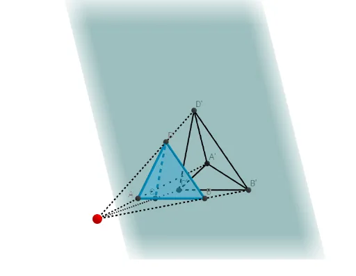
This example demonstrates the Schlegel diagram of a regular tetrahedron, a method of representing a 3D polyhedron by projecting it onto a 2D plane, showing the connectivity of vertices, edges, and faces. The core mathematical concepts include solid geometry, polyhedral projection, and the structure of a tetrahedron (four triangular faces, six edges, four vertices). The construction uses GeoGebra commands such as Circle, Intersect, Rotate, Point, Tetrahedron, Midpoint, Segment, Line, OrthogonalPlane, and Polygon to build the tetrahedron and its faces (e.g., zijvlakABC), with auxiliary points (E, F, G, H) and lines (f, g, h) to achieve the projection. This is suitable for high school or early university students learning about 3D-to-2D representations, and also useful for introductory computer graphics or topology courses.
GeoGebra Commands & Parameters
Circle(O, 1, xOyPlane) → cIntersect(yAxis, c, 2) → ARotate(A, 90°) → BPoint(Circle[Midpoint[A, B], (Distance[A, B] * sqrt(3) / 2), Segment[A, B]]) → CTetrahedron(A, B, C) → a, D, RibbeCD, RibbeBD, zijvlakABC, zijvlakACD, zijvlakABD, zijvlakBCD, RibbeAC, RibbeAB, RibbeBC, RibbeADMidpoint(RibbeBC) → ESegment(D, E) → fMidpoint(RibbeCD) → FSegment(B, F) → gIntersect(g, f) → GLine(A, G) → hPoint(h) → HOrthogonalPlane(H, h) → bPoint(h) → ILine(I, D) → iLine(I, B) → jLine(I, C) → kIntersect(k, b) → JIntersect(i, b) → KIntersect(j, b) → LSegment(I, H) → lSegment(I, J) → mSegment(I, K) → nSegment(I, L) → pPolygon(J, L, K) → driehoek1, k_1, j_1, l_1Segment(J, H) → qSegment(H, K) → rSegment(H, L) → s
AI Drawing Prompt Reference
Construct a 2D Schlegel diagram of a regular tetrahedron by first setting up a base planar reference using a circle and symmetric placements to obtain three key vertices A, B, and C with the needed regular-tetrahedron relations. Use these three points as vertices to form the tetrahedron and keep its edge and face connectivity. Compute midpoints of selected tetrahedron edges to create auxiliary points, then draw connecting segments and determine their intersections to obtain the projected backbone. Use the resulting lines, intersection points, and projected vertices to draw a planar arrangement of multiple triangular regions whose adjacency matches the tetrahedron’s faces, including the internal and boundary edges of the Schlegel diagram.
The prompt above was compiled from the original drawing commands and is for reference only.