
Robotic Arm Simulation
Loading the math board and drawing, please wait…
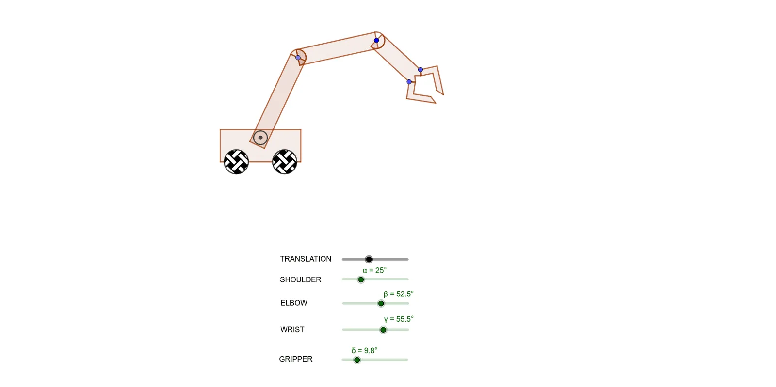
This example uses GeoGebra to simulate a robotic arm, demonstrating the close relationship between mathematics and engineering. It involves core mathematical concepts such as rotation, geometric transformations, translation, and trigonometry. Using commands like Polygon, Point, CircleSector, Intersect, Segment, Circle, Rotate, Vector, Translate, Midpoint, CircleArc, Line, and OrthogonalLine, a dynamic robotic arm model is constructed. Suitable for STEM educational activities in middle school.
GeoGebra Commands & Parameters
Polygon(A, B, C, D) → q1, a, b, c, dPolygon(E, F, G, H) → q2, e, f, g, hPoint(h) → ICircleSector(I, H, E) → kPoint(e) → JIntersect(d, g) → KSegment(J, K) → iIntersect(f, g) → LIntersect(d, e) → MSegment(L, M) → jIntersect(j, i) → NCircle(N, O) → pRotate(E, (-α), N) → E'Rotate(F, (-α), N) → F'Rotate(G, (-α), N) → G'Rotate(H, (-α), N) → H'Polygon(E', F', G', H') → q2', e', f', g', h'Rotate(k, (-α), N) → k'Rotate(I, (-α), N) → I'Point(b) → PCircle(P, 0.75) → qPoint(b) → QCircle(Q, 0.75) → rVector(Q, P1) → uTranslate(A, u) → A'Translate(B, u) → B'Translate(C, u) → C'Translate(D, u) → D'Polygon(A', B', C', D') → q1', a', b', c', d'Translate(E', u) → E''Translate(F', u) → F''Translate(G', u) → G''Translate(H', u) → H''Polygon(E'', F'', G'', H'') → q2'', e'', f'', g'', h''Translate(k', u) → k''Translate(I', u) → I''Translate(p, u) → p'Translate(N, u) → N'Translate(r, u) → r'Translate(q, u) → q'Translate(P, u) → P'Translate(Q, u) → Q'Polygon(E, H, S, T) → q3, e_1, h_1, s, tRotate(E, (-α), N) → E'_1Rotate(H, (-α), N) → H'_1Rotate(S, (-α), N) → S'Rotate(T, (-α), N) → T'Polygon(E'_1, H'_1, S', T') → q3', e'_1, h'_1, s', t'Translate(E'_1, u) → UTranslate(H'_1, u) → VTranslate(S', u) → S''Translate(T', u) → T''Polygon(U, V, S'', T'') → q3'', u_1, v, s'', t''Rotate(U, (-β), I'') → U'Rotate(V, (-β), I'') → V'Rotate(S'', (-β), I'') → S'''Rotate(T'', (-β), I'') → T'''Polygon(U', V', S''', T''') → q3''', u', v', s''', t'''Rotate(k'', (-β), I'') → k'''Polygon(T, S, W, Z) → q4, t_1, s_1, w, z_1Rotate(T, (-α), N) → T'_1Rotate(S, (-α), N) → S'_1Rotate(W, (-α), N) → W'Rotate(Z, (-α), N) → Z'Polygon(T'_1, S'_1, W', Z') → q4', t'_1, s'_1, w', z'Translate(T'_1, u) → A_1Translate(S'_1, u) → B_1Translate(W', u) → W''Translate(Z', u) → Z''Polygon(A_1, B_1, W'', Z'') → q4'', a_1, b_1, w'', z''Rotate(A_1, (-β), I'') → C_1Rotate(B_1, (-β), I'') → D_1Rotate(W'', (-β), I'') → W'''Rotate(Z'', (-β), I'') → Z'''Polygon(C_1, D_1, W''', Z''') → q4''', c_1, d_1, w''', z'''Midpoint(s''') → E_1Rotate(C_1, (-γ), E_1) → F_1Rotate(D_1, (-γ), E_1) → G_1Rotate(W''', (-γ), E_1) → H_1Rotate(Z''', (-γ), E_1) → I_1Polygon(F_1, G_1, H_1, I_1) → q5, f_1, g_1, h_2, i_1Midpoint(s) → J_1CircleArc(J_1, S, T) → k_1Rotate(k_1, (-α), N) → p_1Rotate(J_1, (-α), N) → K_1Translate(K_1, u) → L_1Translate(p_1, u) → q_1Rotate(q_1, (-β), I'') → r_1Rotate(r_1, (-γ), E_1) → c_2Rotate(L_1, (-β), I'') → M_1Midpoint(w) → N_1Polygon(N_1, W, O_1) → t1, o_1, n_1, w_1Polygon(Z, N_1, P_1) → t2, p_2, z_2, n_2Circle(W, O_1) → d_2Point(d_2) → Q_1Polygon(O_1, W, Q_1) → t3, q_2, o_2, w_2Line(W, Q_1) → lOrthogonalLine(W, l) → mOrthogonalLine(Q_1, l) → nPoint(m) → R_1OrthogonalLine(R_1, m) → j_1Point(m) → S_1Line(S_1, j_1) → l_1Point(l_1) → T_1Point(j_1) → U_1Intersect(n, l_1) → V_1Polygon(W, R_1, U_1, T_1, V_1, Q_1) → poly1, w_3, r_2, u_2, t_2, v_1, q_3Line(T_1, N_1) → m_1Circle(Z, P_1) → e_2Point(e_2) → W_1Polygon(Z, P_1, W_1) → t4, w_4, z_3, p_3Line(Z, W_1) → f_2OrthogonalLine(Z, f_2) → g_2OrthogonalLine(W_1, f_2) → i_2Point(i_2) → Z_1OrthogonalLine(Z_1, i_2) → j_2Point(g_2) → A_2OrthogonalLine(A_2, g_2) → k_2Point(k_2) → B_2Point(j_2) → C_2Polygon(W_1, Z_1, C_2, B_2, A_2, Z) → poly2, w_5, z_4, c_3, b_2, a_2, z_5Rotate(N_1, (-α), N) → D_2Rotate(W, (-α), N) → W'_1Rotate(O_1, (-α), N) → E_2Polygon(D_2, W'_1, E_2) → t1', e_3, d_3, w'_1Rotate(W, (-α), N) → W'_2Rotate(R_1, (-α), N) → F_2Rotate(U_1, (-α), N) → G_2Rotate(T_1, (-α), N) → H_2Rotate(V_1, (-α), N) → I_2Rotate(Q_1, (-α), N) → J_2Polygon(W'_2, F_2, G_2, H_2, I_2, J_2) → poly1', w'_2, f_3, g_3, h_3, i_3, j_3Rotate(Z, (-α), N) → Z'_1Rotate(N_1, (-α), N) → K_2Rotate(P_1, (-α), N) → L_2Polygon(Z'_1, K_2, L_2) → t2', l_2, z'_1, k_3Rotate(W_1, (-α), N) → M_2Rotate(Z_1, (-α), N) → N_2Rotate(C_2, (-α), N) → O_2Rotate(B_2, (-α), N) → P_2Rotate(A_2, (-α), N) → Q_2Rotate(Z, (-α), N) → Z'_2Polygon(M_2, N_2, O_2, P_2, Q_2, Z'_2) → poly2', m_2, n_3, o_3, p_4, q_4, z'_2Translate(M_2, u) → R_2Translate(N_2, u) → S_2Translate(O_2, u) → T_2Translate(P_2, u) → U_2Translate(Q_2, u) → V_2Translate(Z'_2, u) → W_2Polygon(R_2, S_2, T_2, U_2, V_2, W_2) → poly2'', r_3, s_2, t_3, u_3, v_2, w_6Translate(D_2, u) → Z_2Translate(W'_1, u) → A_3Translate(E_2, u) → B_3Polygon(Z_2, A_3, B_3) → t1'', b_3, z_6, a_3Translate(W'_2, u) → C_3Translate(F_2, u) → D_3Translate(G_2, u) → E_3Translate(H_2, u) → F_3Translate(I_2, u) → G_3Translate(J_2, u) → H_3Polygon(C_3, D_3, E_3, F_3, G_3, H_3) → poly1'', c_4, d_4, e_4, f_4, g_4, h_4Translate(Z'_1, u) → I_3Translate(K_2, u) → J_3Translate(L_2, u) → K_3Polygon(I_3, J_3, K_3) → t2'', k_4, i_4, j_4Rotate(C_3, (-β), I'') → L_3Rotate(D_3, (-β), I'') → M_3Rotate(E_3, (-β), I'') → N_3Rotate(F_3, (-β), I'') → O_3Rotate(G_3, (-β), I'') → P_3Rotate(H_3, (-β), I'') → Q_3Polygon(L_3, M_3, N_3, O_3, P_3, Q_3) → poly1''', l_3, m_3, n_4, o_4, p_5, q_5Rotate(R_2, (-β), I'') → R_3Rotate(S_2, (-β), I'') → S_3Rotate(T_2, (-β), I'') → T_3Rotate(U_2, (-β), I'') → U_3Rotate(V_2, (-β), I'') → V_3Rotate(W_2, (-β), I'') → W_3Polygon(R_3, S_3, T_3, U_3, V_3, W_3) → poly2''', r_4, s_3, t_4, u_4, v_3, w_7Rotate(Z_2, (-β), I'') → Z_3Rotate(A_3, (-β), I'') → A_4Rotate(B_3, (-β), I'') → B_4Polygon(Z_3, A_4, B_4) → t1''', b_4, z_7, a_4Rotate(I_3, (-β), I'') → C_4Rotate(J_3, (-β), I'') → D_4Rotate(K_3, (-β), I'') → E_4Polygon(C_4, D_4, E_4) → t2''', e_5, c_5, d_5Rotate(R_3, (-γ), E_1) → F_4Rotate(S_3, (-γ), E_1) → G_4Rotate(T_3, (-γ), E_1) → H_4Rotate(U_3, (-γ), E_1) → I_4Rotate(V_3, (-γ), E_1) → J_4Rotate(W_3, (-γ), E_1) → K_4Polygon(F_4, G_4, H_4, I_4, J_4, K_4) → poly3, f_5, g_5, h_5, i_5, j_5, k_5Rotate(C_4, (-γ), E_1) → L_4Rotate(D_4, (-γ), E_1) → M_4Rotate(E_4, (-γ), E_1) → N_4Polygon(L_4, M_4, N_4) → t5, n_5, l_4, m_4Rotate(L_3, (-γ), E_1) → O_4Rotate(M_3, (-γ), E_1) → P_4Rotate(N_3, (-γ), E_1) → Q_4Rotate(O_3, (-γ), E_1) → R_4Rotate(P_3, (-γ), E_1) → S_4Rotate(Q_3, (-γ), E_1) → T_4Polygon(O_4, P_4, Q_4, R_4, S_4, T_4) → poly4, o_5, p_6, q_6, r_5, s_4, t_5Rotate(Z_3, (-γ), E_1) → U_4Rotate(A_4, (-γ), E_1) → V_4Rotate(B_4, (-γ), E_1) → W_4Polygon(U_4, V_4, W_4) → t6, w_8, u_5, v_4Rotate(O_4, (-δ), H_1) → Z_4Rotate(P_4, (-δ), H_1) → A_5Rotate(Q_4, (-δ), H_1) → B_5Rotate(R_4, (-δ), H_1) → C_5Rotate(S_4, (-δ), H_1) → D_5Rotate(T_4, (-δ), H_1) → E_5Polygon(Z_4, A_5, B_5, C_5, D_5, E_5) → poly4', z_8, a_5, b_5, c_6, d_6, e_6Rotate(F_4, δ, I_1) → F_5Rotate(G_4, δ, I_1) → G_5Rotate(H_4, δ, I_1) → H_5Rotate(I_4, δ, I_1) → I_5Rotate(J_4, δ, I_1) → J_5Rotate(K_4, δ, I_1) → K_5Polygon(F_5, G_5, H_5, I_5, J_5, K_5) → poly3', f_6, g_6, h_6, i_6, j_6, k_6Polygon(M_5, N_5, L_5, O_5) → q6, m_5, n_6, l_5, o_6Point(n_6) → R_5Polygon(N_5, P_5, Q_5, R_5) → q7, n_7, p_7, q_7, r_6Polygon(P_5, S_5, T_5, U_5) → q8, p_8, s_5, t_6, u_6Segment(L_5, R_5) → l_6Segment(S_5, Q_5) → m_6Point(q_7) → Z_5Point(q_7) → A_6Polygon(V_5, W_5, Z_5, A_6) → q9, v_5, w_9, z_9, a_6
AI Drawing Prompt Reference
Draw a simulation of a robotic arm, including two quadrilaterals and multiple circles, lines, and segments to demonstrate rotation and geometric transformations. Start by creating a basic robotic arm structure with two quadrilaterals, then use rotation and intersection to define key points, adding circles and lines to represent joints and connections. Next, translate the entire structure along a vector and rotate parts of it to simulate arm movement. Finally, add auxiliary circles and lines to complete the image, showcasing the connection between mathematics and engineering.
The prompt above was compiled from the original drawing commands and is for reference only.