
Rectangular Prism: Construction and Volume Integration
Loading the math board and drawing, please wait…
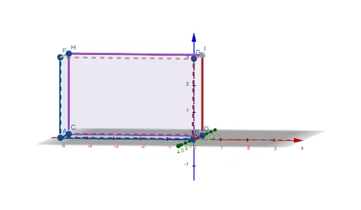
This GeoGebra example constructs a three-dimensional rectangular prism (cuboid) to illustrate its geometric structure and the concept of volume via integration or subtraction. Core mathematical concepts include the definition of a prism, the arrangement of faces and edges, and the relationship between geometric volume and integral calculus. The construction uses Point commands to create vertices (A, B, C, etc.), Segment commands for edges (f, g, h, etc.), and Polygon commands for faces (q1, q2, etc.), with auxiliary objects (F, G, H, I, etc.) to complete the 3D model. It is suitable for high school or early college students learning solid geometry and introductory calculus, helping them visualize how a rectangular prism can be parameterized and how its volume relates to integration.
GeoGebra Commands & Parameters
Point(xAxis) → APoint(xAxis) → BSegment(A, B) → fSegment(A, C) → gSegment(C, D) → hSegment(D, B) → iPolygon(A, B, D, C) → q1, a, b, d, cSegment(G, I) → jSegment(I, H) → kSegment(H, F) → lSegment(F, G) → mSegment(G, B) → nSegment(F, A) → pSegment(H, C) → qSegment(D, I) → rPolygon(F, H, C, A) → q2, f_1, h_1, c_1, a_1Polygon(F, G, B, A) → q3, f_2, g_1, b_1, a_2Polygon(G, I, H, F) → q4, g_2, i_1, h_2, f_3Polygon(H, I, D, C) → q5, h_3, i_2, d_1, c_2Polygon(I, G, B, D) → q6, i_3, g_3, b_2, d_2
AI Drawing Prompt Reference
Draw a rectangular prism with 6 faces and 12 edges. Start by creating points A and B on the x-axis and connecting them with line segment f. Then create points C and D, connect C and D with line segment h, connect A and C with line segment g, and connect D and B with line segment i. Use points A, B, C, and D to form the base face q1. Next, create points F, G, H, and I, connect these points to form the side faces q2, q3, q4, q5, and q6, and the auxiliary lines j, k, l, m, n, p, q, and r.
The prompt above was compiled from the original drawing commands and is for reference only.