
Projectile Motion: Parabolic Trajectory with Parameter Decomposition
Loading the math board and drawing, please wait…
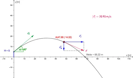
This GeoGebra example demonstrates the complete geometric modeling of oblique projectile motion (schiefer Wurf), showing the parabolic path of an object under gravity. Core mathematical concepts include quadratic functions (parabolic equations), vector decomposition (horizontal and vertical components of initial velocity), angles (launch angle and impact angle), and kinematic relationships between displacement and time. Construction highlights: the Function command defines the parabolic function g, Vector commands create the initial velocity vector v_0 and its components v_x and v_y, Intersect finds the trajectory's ground intersection, Segment draws displacement lines, Root solves for landing time, and Angle labels the launch angle α and impact angle β. Sliders for v_0 and α allow dynamic parameter adjustment. This example is ideal for high school physics or mathematics courses covering projectile motion, quadratic graphs, and vector decomposition, as well as introductory calculus for pre-university students, providing an intuitive visualization of how parameter changes affect trajectory shape.
GeoGebra Commands & Parameters
Function((x * tan(α)) - (g / 2 * x^(2) / ((v_0 * cos(α)))^(2)) + H, 0, 300) → wVector(H_1, H_1 + ((v_0 * cos(α)), (v_0 * sin(α)))) → v_1Vector(A, A + (x(v_1), 0)) → v_xVector(A, A + (0, y(v_1) - (g * t))) → v_yVector(A, A + v_x + v_y) → vIntersect(xAxis, yAxis) → BSegment(B, H_1) → aSegment(A + v_x, A + v) → bSegment(A + v_y, A + v) → cRoot(w, 200) → NAngle(Vector[H_1, H_1 + (1, 0)], v_1) → β
AI Drawing Prompt Reference
Draw the parabolic trajectory of a projectile with sliders for initial velocity v_0 and launch angle α. First, create the parabolic function w, then construct the initial velocity vector v_1 and its horizontal and vertical components v_x and v_y. Next, find the intersection point B of the trajectory with the ground, and finally draw displacement segments from the initial point to any point on the trajectory.
The prompt above was compiled from the original drawing commands and is for reference only.