
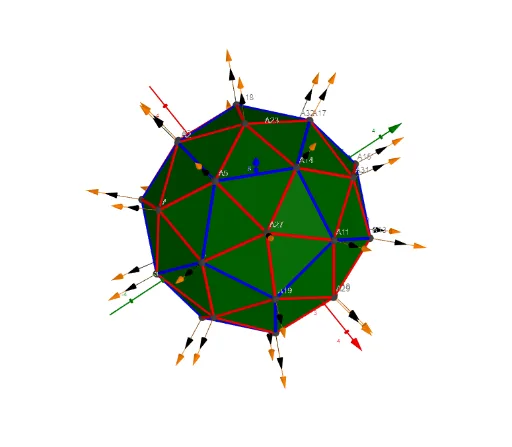
Pentakis Dodecahedron with 32 Vertices: a Sphere-Based Construction
Loading the math board and drawing, please wait…
This example demonstrates a Pentakis Dodecahedron as a sphere-contained solid and highlights its structural feature of having 32 vertices. The key mathematics includes 3D geometry built from regular/dual polyhedral ideas, sphere-based embedding, and parameterized construction of discrete point sets using vectors and sequences. Construction workflow: Sphere is used to create the reference sphere surface; Sequence and TableText generate parameter/index-driven points and their labels; Sum and Zip aggregate multiple geometry components (such as coordinate lists and segment endpoints) into unified collections; Text together with UnicodeToLetter builds readable annotations. The model then connects the generated point sets (e.g., Points00 and related point collections) using Segments to form the visible edges/faces. Vector objects (lVector1, lVector2, lVector3) and auxiliary constructs (including Cm) support direction-dependent or local geometric relationships. Suitable for advanced high-school to early university audiences, especially for lessons on solid geometry, geometric construction, and parameter-driven mathematical visualization.
GeoGebra Commands & Parameters
UnicodeToLetter(34) → u34Text("" + Um1) → txt_pSum(Flatten[Sequence[Append[Sequence[Element[txt_p, i], i, m01(k), m02(k)], " "], k, 1, 5]]) → txtUm1Zip(Vector[a, a + UnitVector[a]], a, Points00) → lVector1Zip(Vector[a, a + (1.5 * UnitVector[b])], a, Points00, b, Wi_Pc) → lVector2Zip(Vector[a, a + (1.5 * UnitVector[b])], a, Points00, b, Wi_P) → lVector3Sphere((0, 0, 0), 5) → sphTableText(Append["i", 1…n], Append[" \fgcolor{orange}{GM :Δφ_i}, rad", l1w], Append["\fgcolor{magenta}{GC :Δφ_i} , rad", l1cw], "v") → text23rZip(Segment[Element[Points00, y(a)], Element[Points00, z(a)]], a, ll1bb(1)) → ll1Zip(Segment[Element[Points00, y(a)], Element[Points00, z(a)]], a, ll1bb(2)) → ll2Zip(Segment[Element[Points00, y(a)], Element[Points00, z(a)]], a, ll1bb(3)) → ll3Zip(Segment[Element[Points00, y(a)], Element[Points00, z(a)]], a, ll1bb(4)) → ll4Zip(Segment[Element[Points00, y(a)], Element[Points00, z(a)]], a, ll1bb(5)) → ll5Zip(Segment[Element[Points00, y(a)], Element[Points00, z(a)]], a, ll1bb(6)) → ll6Zip(Segment[Element[Points00, y(a)], Element[Points00, z(a)]], a, ll1bb(7)) → ll7Zip(Segment[Element[Points00, y(a)], Element[Points00, z(a)]], a, ll1bb(8)) → ll8Zip(Segment[Element[Points00, y(a)], Element[Points00, z(a)]], a, ll1bb(9)) → ll9Zip(Segment[Element[Points00, y(a)], Element[Points00, z(a)]], a, ll1bb(10)) → ll10Sequence(Polygon[Element[Points3D, Element[Element[mm1, f], 1]], Element[Points3D, Element[Element[mm1, f], 2]], Element[Points3D, Element[Element[mm1, f], 3]]], f, 1, Length[mm1]) → poly001
AI Drawing Prompt Reference
Create a 3D reference sphere centered at the origin with radius 5, and generate a discrete set of points suitable for a sphere-contained solid, driven by parameter/index sequences with readable labels. Use vector-based direction relationships to define how neighboring point positions relate to the point set. Then connect selected point pairs with line segments to form the visible edge structure, and build polygonal face outlines by taking triplets from the chosen point sequence to create polygons. Add text annotations that include indexed terms like Δφ_i together with a radius notation, using clear colored emphasis and numbering, to highlight the pentakis dodecahedron’s structural organization.
The prompt above was compiled from the original drawing commands and is for reference only.