
Parallelogram of Forces
Loading the math board and drawing, please wait…
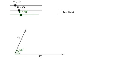
This example illustrates the parallelogram of forces, where the resultant of two forces can be represented by constructing a parallelogram with these forces as adjacent sides. Key mathematical concepts include vectors and geometric construction. GeoGebra commands used include Rotate, Segment, Vector, Translate, Angle, Distance, Midpoint, and others. Suitable for high school physics and mathematics education.
GeoGebra Commands & Parameters
Rotate(G, β, A) → G'Segment(A, B) → fSegment(A, C) → gVector(A, C) → wTranslate(B, w) → B'Segment(C, B') → hSegment(B, B') → iVector(A, B) → aVector(A, B') → bAngle(C, A, B) → αDistance(A, B') → dSegment(A, B') → jMidpoint(j) → DSegment(A, B) → kSegment(A, C) → lMidpoint(k) → EMidpoint(l) → FAngle(C, A, B') → γAngle(B', A, G') → δ
AI Drawing Prompt Reference
Draw a parallelogram of forces: start from a common point, draw two adjacent sides representing two forces in different directions. Complete the parallelogram using these sides, then draw the diagonal from the common point to the opposite vertex as the resultant force. Mark the angle between the two force sides at the common point, and also mark the angle between the resultant diagonal and one of the force sides. Place midpoint markers on both adjacent sides and on the resultant diagonal. Additionally, rotate one of the force sides around the common point by a certain angle to create an auxiliary line, and mark the angle between this auxiliary line and the resultant diagonal. The diagram should clearly illustrate the geometric construction of force composition.
The prompt above was compiled from the original drawing commands and is for reference only.