
Matrix-Controlled Geometric Transformations
Loading the math board and drawing, please wait…
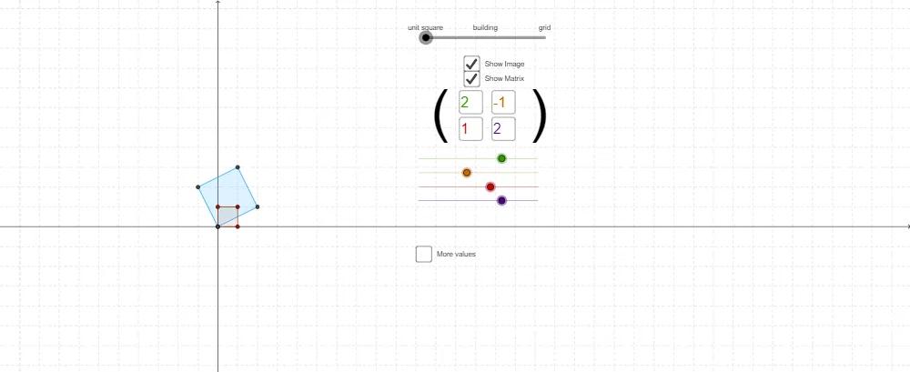
This example visualizes how a matrix-driven transformation maps a polygonal figure into its transformed image, enabling direct comparison of corresponding vertices and shapes. It focuses on the geometric effects of matrix transformations by expressing transformations through coordinate changes and by using construction elements to control direction and reference geometry. The key concepts include matrix transformations as linear operators, vector coordinate mapping, and geometric construction of transformation geometry (e.g., using an axis/angle). Construction is built with GeoGebra commands such as Textfield (parameter entry/display), Polygon (construct poly1 and poly2), Line (reference lines), Mirror (apply reflection-based transformation), Point (control and define vertices/intermediates), and Angle (set or constrain the rotation/reflection orientation). Objects like the labeled points (B, C, D, E, F), input boxes (inputBox1–inputBox4), and parameters (r, s, t, q) drive the mapping, while the diagram (including auxiliary labeled points and the final shapes) helps learners observe how matrices produce concrete geometric changes. Suitable for secondary advanced geometry, linear algebra introduction, and classroom demonstrations.
GeoGebra Commands & Parameters
Textfield(q) → inputBox2Textfield(r) → inputBox1Textfield(s) → inputBox3Textfield(t) → inputBox4Polygon(A, B, C, D, E, F) → poly1, a, b, c, d, e, fPolygon(L, G, H, I, J, K) → poly2, l, g, h, i, j, kPolygon(N, O, Q, P) → q1, n_1, o, q_1, pPolygon(N, S, U, T) → q2, n_2, s_1, u, t_1Line(N, T) → i_1Line(N, S) → j_1Line(S, U) → k_1Line(T, U) → l_1Mirror(j_1, l_1) → m_1Mirror(l_1, j_1) → d_1Mirror(j_1, d_1) → e_1Mirror(i_1, k_1) → a_1Mirror(i_1, a_1) → b_1Mirror(a_1, b_1) → c_1Mirror(b_1, c_1) → i_2Mirror(c_1, i_2) → j_2Mirror(a_1, i_1) → k_2Mirror(i_1, k_2) → l_2Mirror(k_2, l_2) → m_2Mirror(j_1, m_1) → q_2Mirror(m_1, q_2) → r_2Mirror(q_2, r_2) → s_2Mirror(r_2, s_2) → t_2Mirror(s_2, t_2) → a_2Mirror(j_1, e_1) → b_2Mirror(e_1, b_2) → c_2Mirror(b_2, c_2) → d_2Mirror(t_2, a_2) → f_1Mirror(a_2, f_1) → g_1Mirror(f_1, g_1) → h_1Mirror(g_1, h_1) → p_1Mirror(h_1, p_1) → r_1Mirror(c_2, d_2) → f_2Mirror(d_2, f_2) → g_2Mirror(f_2, g_2) → h_2Mirror(g_2, h_2) → p_2Mirror(i_2, j_2) → e_2Mirror(j_2, e_2) → f_3Mirror(e_2, f_3) → g_3Mirror(l_2, m_2) → h_3Mirror(m_2, h_3) → i_3Mirror(h_3, i_3) → j_3Mirror(i_3, j_3) → k_3Mirror(i_3, k_3) → l_3Mirror(j_3, k_3) → m_3Mirror(p_1, r_1) → n_3Mirror(r_1, n_3) → p_3Mirror(n_3, p_3) → q_3Mirror(p_3, q_3) → r_3Mirror(q_3, r_3) → s_3Mirror(r_3, s_3) → t_3Mirror(s_3, t_3) → a_3Mirror(t_3, a_3) → b_3Mirror(h_2, p_2) → c_3Point(xAxis) → VAngle(V, N, T) → αPolygon(N_{1}, O_{1}, Q_{1}, P_{1}) → q1_{1}, n_{4}, o_{1}, q_{4}, p_{4}Polygon(N_{2}, O_{2}, Q_{2}, P_{2}) → q1_{2}, n_{5}, o_{2}, q_{5}, p_{5}
AI Drawing Prompt Reference
Visualize a matrix-driven geometric transformation that maps a polygonal figure to its transformed image, allowing direct comparison of corresponding vertices and shapes. Draw two polygons, one as the original figure and the other as the transformed image. Then, use a series of mirror operations to illustrate the transformation process, including constructing reference lines and auxiliary shapes, to finally present a comparative view of the original and transformed figures, emphasizing the geometric significance of matrix transformations.
The prompt above was compiled from the original drawing commands and is for reference only.