
LMOrigami22 Belt Cube
Loading the math board and drawing, please wait…
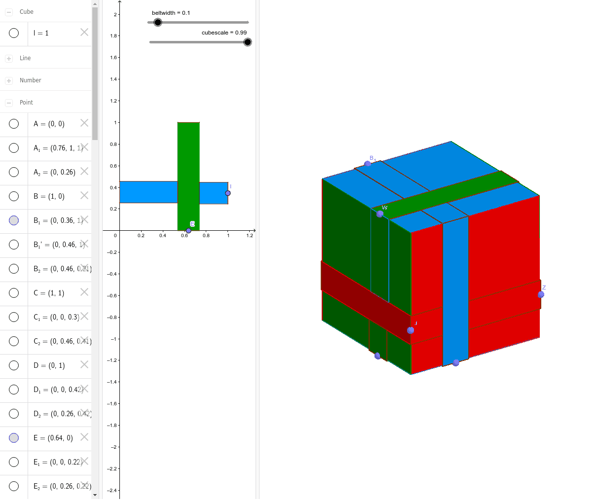
This example demonstrates a belt cube constructed from points, polygons, and cubes. The core mathematical concepts involved include solid geometry, symmetry, and geometric construction. Key construction steps use GeoGebra commands such as Point, Intersect, Polygon, OrthogonalLine, Mirror, Cube, Line, and Dilate; objects include beltwidth, C, D, A, B, poly1, a, b, c, d, E, e, F, f, G, H, F', H', poly2, f', f_1, h, h', I, J, g, i, K, K', J', poly3, k, j, j', k', L, l, O, P, Q. Suitable for high school and above learning solid geometry and geometric construction.
GeoGebra Commands & Parameters
Point(yAxis) → DIntersect(xAxis, yAxis) → APoint(xAxis) → BPolygon(A, B, C, D) → poly1, a, b, c, dPoint(a) → EOrthogonalLine(E, a) → eOrthogonalLine(F, a) → fIntersect(e, c) → GIntersect(f, c) → HMirror(F, e) → F'Mirror(H, e) → H'Polygon(F', F, H, H') → poly2, f', f_1, h, h'Point(b) → IOrthogonalLine(I, b) → gOrthogonalLine(J, b) → iIntersect(i, f_1) → KMirror(K, g) → K'Mirror(J, g) → J'Polygon(K, J, J', K') → poly3, k, j, j', k'Intersect(d, yAxis) → LCube(B, C, poly1) → l, O, faceCOSR, faceOPTS, faceQRST, edgeBP, edgeBC, edgeCO, edgeOP, edgeBQ, edgePT, edgeQT, P, edgeQR, edgeCR, edgeRS, edgeOS, edgeST, Q, R, S, T, faceBCOP, faceBPTQ, faceBCRQPoint(edgeBQ) → UPoint(edgeQT) → WPoint(edgeCR) → ZPoint(edgeST) → B_1Point(edgePT) → C_1OrthogonalLine(U, edgeBQ, faceBPTQ) → pMirror(U', p) → U''OrthogonalLine(U', edgeBQ, faceBPTQ) → qOrthogonalLine(U'', edgeBQ, faceBPTQ) → rIntersect(q, edgePT) → D_1Intersect(edgePT, r) → E_1Polygon(E_1, U'', U', D_1) → poly5, e_1, u'', u', d_1OrthogonalLine(J', b, faceBCRQ) → sOrthogonalLine(J, b, faceBCRQ) → tIntersect(t, edgeQR) → F_1Intersect(s, edgeQR) → G_1Polygon(G_1, F_1, J, J') → poly6, g_1, f_2, j_1, j'_1OrthogonalLine(U', edgeBQ, faceBCRQ) → mOrthogonalLine(U'', edgeBQ, faceBCRQ) → nIntersect(m, j'_1) → MIntersect(n, j'_1) → NPolygon(U'', N, M, U') → poly4, u''_1, n_1, m_1, u'_1OrthogonalLine(W, edgeQT, faceQRST) → a_1Mirror(W', a_1) → W''OrthogonalLine(W'', edgeQT, faceQRST) → b_1OrthogonalLine(W', edgeQT, faceQRST) → c_1Intersect(b_1, edgeRS) → VIntersect(c_1, edgeRS) → A_1Polygon(V, A_1, W', W'') → poly7, v, a_2, w', w''OrthogonalLine(W'', edgeQT, faceBPTQ) → h_1OrthogonalLine(W', edgeQT, faceBPTQ) → i_1OrthogonalLine(F, a, faceBPTQ) → k_1OrthogonalLine(F', a, faceBPTQ) → l_1Intersect(e_1, l_1) → H_1Intersect(k_1, e_1) → I_1Intersect(i_1, u') → J_1Intersect(h_1, u') → K_1Polygon(W'', K_1, J_1, W') → poly8, w''_1, k_2, j_2, w'_1Polygon(F', F, I_1, H_1) → poly9, f'_1, f_3, i_2, h_2OrthogonalLine(F_1, edgeQR, faceQRST) → p_1OrthogonalLine(G_1, edgeQR, faceQRST) → q_1Intersect(p_1, a_2) → L_1Intersect(q_1, a_2) → M_1Polygon(M_1, G_1, F_1, L_1) → poly10, m_2, g_2, f_4, l_2OrthogonalLine(Z, edgeCR, faceCOSR) → r_1Mirror(Z', r_1) → Z''OrthogonalLine(Z', edgeCR, faceCOSR) → s_1OrthogonalLine(Z'', edgeCR, faceCOSR) → t_1Intersect(s_1, edgeOS) → N_1Intersect(t_1, edgeOS) → O_1Polygon(Z'', O_1, N_1, Z') → poly11, z'', o_1, n_2, z'OrthogonalLine(A_1, edgeRS, faceCOSR) → b_2OrthogonalLine(V, edgeRS, faceCOSR) → c_2OrthogonalLine(H, c, faceCOSR) → d_2OrthogonalLine(H', c, faceCOSR) → e_2Intersect(t_1, d_2) → P_1Intersect(t_1, e_2) → Q_1Intersect(c_2, s_1) → R_1Intersect(s_1, b_2) → S_1Polygon(S_1, R_1, V, A_1) → poly12, s_2, r_2, v_1, a_3Polygon(H, H', Q_1, P_1) → poly13, h_3, h'_1, q_2, p_2OrthogonalLine(Z', edgeCR, faceBCRQ) → t_2OrthogonalLine(Z'', edgeCR, faceBCRQ) → b_3Intersect(t_2, f_2) → T_1Intersect(b_3, f_2) → U_1Polygon(U_1, Z'', Z', T_1) → poly14, u_1, z''_1, z'_1, t_3OrthogonalLine(B_1, edgeST, faceOPTS) → c_3OrthogonalLine(B_1', edgeST, faceOPTS) → d_3Mirror(B_1', c_3) → V_1OrthogonalLine(V_1, edgeST, faceOPTS) → e_3Intersect(d_3, d) → W_1Intersect(d, edgeOP) → Z_1Intersect(e_3, d) → A_2Polygon(W_1, A_2, V_1, B_1') → poly15, w_1, a_4, v_2, b_1'OrthogonalLine(O_1, edgeOS, faceOPTS) → g_3OrthogonalLine(N_1, edgeOS, faceOPTS) → i_3OrthogonalLine(E_1, edgePT, faceOPTS) → j_3OrthogonalLine(D_1, edgePT, faceOPTS) → k_3Intersect(d_3, g_3) → B_2Intersect(i_3, d_3) → C_2Intersect(e_3, k_3) → D_2Intersect(e_3, j_3) → E_2Polygon(O_1, B_2, C_2, N_1) → poly16, o_2, b_4, c_4, n_3Polygon(E_1, E_2, D_2, D_1) → poly17, e_4, e_5, d_4, d_5OrthogonalLine(B_1', edgeST, faceQRST) → l_3OrthogonalLine(V_1, edgeST, faceQRST) → m_3Intersect(l_3, w'') → F_2Intersect(m_3, w'') → G_2Polygon(B_1', V_1, G_2, F_2) → poly18, b_5, v_3, g_4, f_5OrthogonalLine(W_1, d, xOyPlane) → p_3OrthogonalLine(A_2, d, xOyPlane) → q_3Intersect(p_3, h') → H_2Intersect(q_3, h') → I_2Polygon(W_1, H_2, I_2, A_2) → poly19, w_2, h_4, i_4, a_5Line(A, R) → r_3Line(T, C) → s_3Intersect(s_3, r_3) → J_2Dilate(faceBCOP, cubescale, J_2) → faceBCOP'Dilate(faceBCRQ, cubescale, J_2) → faceBCRQ'Dilate(faceBPTQ, cubescale, J_2) → faceBPTQ'Dilate(faceCOSR, cubescale, J_2) → faceCOSR'Dilate(faceOPTS, cubescale, J_2) → faceOPTS'Dilate(faceQRST, cubescale, J_2) → faceQRST'
AI Drawing Prompt Reference
Draw a belt cube constructed from points and polygons, demonstrating solid geometry and symmetry. Start by creating a quadrilateral, then use orthogonal lines and mirror operations from its vertices to form multiple geometric shapes, including cubes and polygons. Combine these shapes to form a complex 3D structure, highlighting the process of geometric construction and symmetry.
The prompt above was compiled from the original drawing commands and is for reference only.