
Geometric Construction Guided Optimization Example
Loading the math board and drawing, please wait…
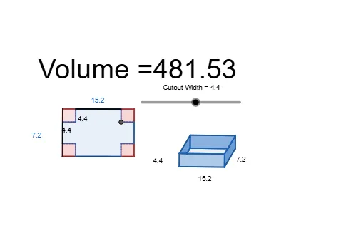
This example demonstrates an optimization workflow driven by geometric construction: within a configuration constrained by lines, circles, and a polygon, a target quantity defined from geometric measurements (e.g., distances or angles) changes as construction parameters vary, and an optimal configuration can be identified visually. The key mathematical ideas include optimization in a constrained geometric setting, distance and angle measurement, and generating equivalent or symmetric configurations using construction tools. Construction-wise, it is built from GeoGebra commands such as Line and OrthogonalLine to create guiding lines, Point for defining key vertices, Segment and Polygon to form the polygonal region, Circle together with Intersect to locate intersection points, Distance to compute the measurable quantities, Rotate to transform the figure, and Angle to extract the angular relations that participate in the optimization. Suitable for secondary school to early university students, and useful for teaching how geometric models connect with optimization-style reasoning.
GeoGebra Commands & Parameters
Line(A, B) → fOrthogonalLine(A, f) → gPoint(Circle[A, 24]) → CSegment(A, C) → hPoint(Circle[A, 16]) → DSegment(A, D) → iCircle(A, D) → cIntersect(c, g, 2) → EOrthogonalLine(E, g) → jOrthogonalLine(C, f) → kSegment(E, A) → lSegment(A, C) → mIntersect(j, k) → FSegment(C, F) → nSegment(F, E) → pCircle(A, Cutout) → dCircle(E, Cutout) → eCircle(F, Cutout) → qCircle(C, Cutout) → rIntersect(e, l, 1) → GIntersect(q, n, 1) → HSegment(G, H) → sIntersect(r, n, 1) → IIntersect(d, l, 1) → JSegment(I, J) → tIntersect(d, h, 1) → KIntersect(e, p, 1) → LSegment(K, L) → aIntersect(q, p, 1) → MIntersect(r, h, 1) → NSegment(M, N) → bIntersect(s, a) → OIntersect(s, b) → PIntersect(t, b) → QIntersect(t, a) → RSegment(G, O) → f_1Segment(O, L) → g_1Segment(P, H) → i_1Segment(P, M) → j_1Segment(Q, I) → l_1Segment(R, J) → p_1Segment(R, K) → q_1Segment(Q, N) → r_1Polygon(G, O, L, E) → q1, g_2, o, l_2, e_1Polygon(J, R, K, A) → q2, j_2, r_2, k_1, a_1Polygon(N, Q, I, C) → q3, n_1, q_2, i_2, c_1Polygon(M, F, H, P) → q4, m_1, f_2, h_1, p_2Polygon(G, O, R, J, L, M, P, H, I, Q, N, K) → poly1, g_3, k_2, r_3, j_3, o_1, l_3, m_2, p_3, h_2, i_3, q_3, n_2Distance(J, G) → distanceJGDistance(L, M) → distanceLMSegment(G, J) → s_1Segment(L, M) → t_1Segment(G, E) → b_1Segment(J, A) → d_1Segment(G, J) → s_2Segment(L, M) → t_2Line(T, U) → a_2Rotate(T, -120°, U) → T'Angle(T', U, T) → αLine(U, T') → b_2Circle(U, j_3) → c_2Circle(U, l_3) → d_2Intersect(d_2, b_2, 2) → VIntersect(c_2, b_2, 2) → WLine(W, a_2) → e_2Intersect(d_2, a_2, 1) → ZLine(Z, b_2) → f_3Circle(U, g_1) → c_3OrthogonalLine(U, a_2) → h_3Line(W, h_3) → k_3Line(Z, h_3) → m_3Intersect(e_2, f_3) → A_1Line(A_1, h_3) → n_3Intersect(c_3, h_3, 2) → B_1Line(B_1, b_2) → s_3Line(B_1, a_2) → t_3Intersect(m_3, t_3) → C_1Line(C_1, s_3) → a_3Intersect(k_3, s_3) → D_1Line(D_1, t_3) → b_3Intersect(n_3, a_3) → E_1Intersect(f_3, t_3) → F_1Intersect(e_2, s_3) → G_1Segment(Z, U) → d_3Segment(U, B_1) → e_3Segment(U, W) → f_4Segment(W, D_1) → g_4Segment(D_1, G_1) → h_4Segment(G_1, B_1) → i_4Segment(B_1, F_1) → j_4Segment(F_1, C_1) → k_4Segment(C_1, Z) → l_4Segment(C_1, E_1) → m_4Segment(E_1, A_1) → n_4Segment(A_1, F_1) → p_4Segment(E_1, D_1) → q_4Segment(G_1, A_1) → r_4Polygon(F_1, C_1, E_1, A_1) → q5, s_4, t_4, a_4, b_4Polygon(E_1, D_1, G_1, A_1) → q6, c_4, d_4, e_4, f_5Polygon(A_1, G_1, B_1, F_1) → q7, g_5, h_5, i_5, j_5Polygon(B_1, D_1, W, U) → q8, k_5, l_5, w, uPolygon(C_1, Z, U, B_1) → q9, m_5, z_1, u_1, n_5
AI Drawing Prompt Reference
Draw a geometric figure composed of lines, circles, and polygons. Start by drawing two parallel lines f and g. Then, take points C and D on circles, and connect AC and AD to form segments. Next, draw circle c and find its intersection E with g. Use rotations and perpendicular lines to construct a series of intersection points F, G, H, I, J, K, L, M, and N. Finally, connect these points to form several polygons, including quadrilateral GOLE, quadrilateral JRAK, quadrilateral NQIC, and quadrilateral MFHP.
The prompt above was compiled from the original drawing commands and is for reference only.