
GeoGebra 3D Geometry and Vector Construction Example
Loading the math board and drawing, please wait…
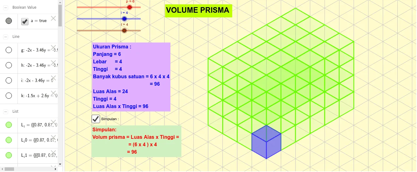
This example demonstrates constructing geometric figures such as triangles, vectors, and surfaces in three-dimensional space. Key mathematical concepts include vector operations, solid geometry, and geometric construction. The construction involves using commands like Point, Segment, Line, Intersect, Vector, and Polygon, along with objects such as A, B, C, D, E, F. It is suitable for high school students or math enthusiasts to learn geometric construction and spatial visualization.
GeoGebra Commands & Parameters
Point(xAxis) → APoint(yAxis) → BSegment(A, B) → fLine(B, f) → gLine(B, f) → hIntersect(xAxis, yAxis) → CLine(C, f) → iPoint(i) → DSegment(E, F) → jLine(E, j) → kVector(C, F) → uPoint(k) → HPolygon(G, H, I, J) → q1, g_1, h_1, i_1, j_1Point(k) → KPolygon(K, L, I, H) → q2, k_1, l_2, i_2, h_2Polygon(L, M, J, I) → q3, l_1, m, j_2, i_3Point(yAxis) → NVector(C, N) → vPoint(i) → OVector(C, O) → wSequence(Translate[Element[L_1, 1], Vector[(i * v)]], i, 1, t - 1) → L_5Sequence(Translate[Element[L_2, 1], Vector[(i * v)]], i, 1, t - 1) → L_6Sequence(Translate[Element[L_4, 1], Vector[(i * u)]], i, 1, p - 1) → L_9Sequence(Translate[Element[L_3, 1], Vector[(i * w)]], i, 1, l - 1) → L_10Sequence(Translate[L_3, Vector[(v * i)]], i, 1, t - 1) → L_11Sequence(Translate[L_10, Vector[(v * i)]], i, 1, t - 1) → L_12Sequence(Translate[L_4, Vector[(v * i)]], i, 1, t - 1) → L_13
AI Drawing Prompt Reference
Draw a 3D geometric figure including triangles, vectors, and surfaces. Start by creating points A and B on the x-axis and y-axis, then form a segment f connecting A and B. Next, create two lines g and h through B and f, and create a line i through the intersection of x-axis and y-axis C, then create point D through line i. Then, create points E and F, form a segment j connecting E and F, and create a line k through E and j. Next, create vector u from C to F, then create point H through line k. Then, create three quadrilaterals q1, q2, and q3, and finally create vector v from C to N and vector w from C to O, and use v and w for translation operations to generate a series of new segments.
The prompt above was compiled from the original drawing commands and is for reference only.