
Explore 3: Changing Angles
Loading the math board and drawing, please wait…
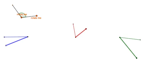
This example demonstrates the effect of angle changes on geometric figures. Key mathematical concepts include trigonometry, geometric transformations, and linear regression. Construction involves GeoGebra commands such as Rotate, Angle, and CircleSector. Suitable for high school students or math enthusiasts to understand geometric transformations and trigonometric relationships.
GeoGebra Commands & Parameters
Rotate(D, 120°, A) → D'Angle(D, A, D') → αRotate(E, 120°, B) → E'Angle(E, B, E') → βRotate(F, 120°, C) → F'Angle(F, C, F') → γCircleSector(A, D, D') → cCircleSector(B, E, E') → dPoint(c) → GPoint(d) → HSegment(G, A) → fSegment(H, B) → gRay(C, F) → hRay(C, F') → iPoint(h) → IPoint(i) → JPoint(h) → G_1Point(h) → H_1Point(h) → I_1Point(h) → J_1Point(i) → A_2Point(i) → F_2Polygon(J, K, V, Z, A_1, B_1, C_1, D_1, E_1, F_1, G_1, F, L, H_1, I_1, J_1, C, L_1, M_1, N_1, O_1, P_1, Q_1, M, R_1, S_1, T_1, U_1, V_1, W_1, Z_1, A_2, B_2, C_2, N, D_2, F', E_2, F_2, O, P, Q, R, T) → poly1, j, t, v, z_1, a_1, b_1, c_1, d_1, e_1, f_1, g_1, k, f_2, h_1, i_1, j_1, c_2, l_1, m_1, n_1, o_1, p_1, l, q_1, r_1, s_1, t_1, u_1, v_1, w_1, s, a_2, b_2, m, a, d_2, f', e_2, b, n, o, p, q, rPoint(poly1) → SSegment(S, C) → eCircle(U, 2) → k_1Point(k_1) → WRotate(W, 120°, U) → W'Angle(W, U, W') → δCircleSector(U, W, W') → g_2Segment(W', U) → h_2Segment(U, W) → i_2Point(i) → K_1Segment(C, K_1) → j_2Segment(E', B) → k_2Segment(D, A) → l_2
AI Drawing Prompt Reference
On a plane, choose base points A, B, and C. Construct D' by rotating point D around A by 120°, then form and display the angle ∠DAD'. Similarly rotate E around B by 120° to get E', and form ∠EBE'. Rotate F around C by 120° to get F', and form ∠FCF'. Build two circular sectors using (A, D, D') and (B, E, E'), then take points generated from these sectors and connect them to A and to B by segments. From C, draw rays toward the corresponding rotated directions, mark the resulting points, and add segments linking the ray endpoints to form a polygonal outline together with the earlier lines, illustrating how changing angles alters the overall geometry.
The prompt above was compiled from the original drawing commands and is for reference only.