
Drawing Cross Sections of a Cube
Loading the math board and drawing, please wait…
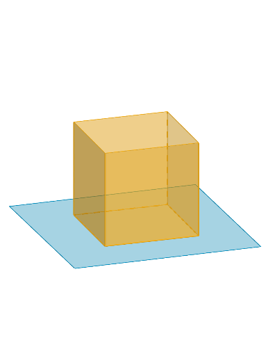
This example demonstrates how to dynamically interact and draw various cross-sections of a cube. It involves core mathematical concepts such as solid geometry, cross-section analysis, and geometric transformations. Key GeoGebra commands used in the construction include Polygon, PointIn, Translate, Rotate, Prism, Plane, IntersectPath, and OrthogonalLine. Suitable for high school geometry teaching and geometric construction learning.
GeoGebra Commands & Parameters
Polygon(B + (-2, -2), B + (2, -2), B + (2, 2), B + (-2, 2)) → poly3, e, f, g, iPointIn(poly3) → CTranslate((0, 0, 0), Vector[B, C]) → APolygon(A + (-4, -4), A + (4, -4), A + (4, 4), A + (-4, 4)) → poly1, a, b, c, dRotate(Rotate[Translate[poly1, Vector[A, A + (0, 0, h)]], (90° * s), A + (0, 0, h), yAxis], (90° * t), A, zAxis) → poly2Prism(Polygon[(2, 2, 0), (2, -2, 0), (-2, -2, 0), (-2, 2, 0)], 4) → m, M, edge1, edge2, edge3, edge4, edge5, edge6, edge7, edge8, N, Q, R, face1, face2, face3, face4, face5Rotate(D, 120°, (0, 0, 0)) → EPolygon(D, E, 3, xOyPlane) → poly4, j, k, l, FPointIn(poly2) → GPointIn(poly2) → HPointIn(poly2) → IPlane(G, I, H) → nIntersectPath(n, m) → poly6, poly5, r, a_1, b_1, c_1, K, L_1, O, P, J, L, p, qRotate(m, 0, zAxis) → m'Rotate(m, 0, zAxis) → m'_1OrthogonalLine(A, n) → d_1
AI Drawing Prompt Reference
Draw a cube and its various cross-sections by different planes. Start by drawing a square base, then generate the other faces of the cube through translation and rotation. Select several points on the cube to define a plane, and find the intersection of this plane with the cube's surface to get the polygon of the cross-section. Finally, rotate the cube and draw its orthogonal lines.
The prompt above was compiled from the original drawing commands and is for reference only.