
Dodecahedron Half Model Kite Right
Loading the math board and drawing, please wait…
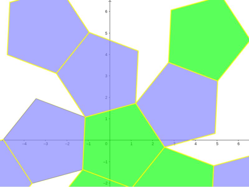
This is a net of a dodecahedron, demonstrating the structure of a dodecahedron. The core mathematical concepts involved include polygons and solid geometry. Using GeoGebra commands such as Point, Dodecahedron, Segment, Rotate, Circle, Center, OrthogonalLine, Polygon, and TableText, the various faces and edges of the dodecahedron can be constructed. Suitable for high school or university solid geometry studies.
GeoGebra Commands & Parameters
Point(Circle[(((1 - sqrt(5)) * A) + ((3 + sqrt(5)) * B)) / 4, (Distance[A, B] * sqrt(10 + (2 * sqrt(5))) / 4), Segment[A, B]]) → CDodecahedron(A, B, C) → a, D, M, N, O, P, Q, R, S, T, faceABCDE, faceAEIOJ, E, faceABFKJ, faceBCGLF, faceCDHMG, faceDEINH, faceINSTO, faceJKPTO, faceFKPQL, faceGLQRM, faceHMRSN, facePQRST, F, edgeAE, edgeAB, edgeBC, edgeCD, edgeDE, edgeAJ, edgeEI, edgeIO, edgeJO, edgeJK, G, edgeFK, edgeBF, edgeFL, edgeGL, edgeCG, edgeGM, edgeHM, edgeDH, edgeHN, edgeIN, H, edgeNS, edgeST, edgeOT, edgePT, edgeKP, edgePQ, edgeLQ, edgeQR, edgeMR, edgeRS, I, J, K, LSegment(U, U + (0, 0, 2)) → bPoint(b) → VRotate(Polygon[A, B, F, K, J], (α * t), Segment[A, B]) → poly1Rotate(Polygon[F, K, P, Q, L], (α * t), Segment[K, F]) → poly2Rotate(Polygon[P, Q, R, S, T], (α * t), Segment[P, Q]) → poly3Rotate(poly2, (α * t), Segment[A, B]) → poly2'Rotate(poly3, (α * t), Segment[K, F]) → poly3'Rotate(poly3', (α * t), Segment[A, B]) → poly3''Circle(A, B, D) → cCenter(c) → WOrthogonalLine(W, Plane[A, B, D]) → dRotate(poly1, 72*°, d) → poly1'Rotate(poly1', 72*°, d) → poly1''Rotate(poly1'', 72*°, d) → poly1'''Rotate(poly1''', 72*°, d) → poly4Rotate(poly2', 72*°, d) → poly2''Rotate(poly2'', 72*°, d) → poly2'''Rotate(poly2''', 72*°, d) → poly5Rotate(poly5, 72*°, d) → poly5'Polygon(A, B, C, D, E) → poly6, a_1, b_1, c_1, d_1, eTableText({{LaTeX[A, true, true]}, {LaTeX[B, true, true]}, {LaTeX[C, true, true]}, {LaTeX[D, true, true]}, {LaTeX[E, true, true]}, {LaTeX[F, true, true]}, {LaTeX[G, true, true]}, {LaTeX[H, true, true]}, {LaTeX[I, true, true]}, {LaTeX[J, true, true]}, {LaTeX[K, true, true]}, {LaTeX[L, true, true]}, {LaTeX[M, true, true]}, {LaTeX[N, true, true]}, {LaTeX[O, true, true]}, {LaTeX[P, true, true]}, {LaTeX[Q, true, true]}, {LaTeX[R, true, true]}, {LaTeX[S, true, true]}, {LaTeX[T, true, true]}, {LaTeX[U, true, true]}, {LaTeX[V, true, true]}, {LaTeX[W, true, true]}}) → text1Rotate(poly2''', 72*°, d) → poly7Rotate(poly1'', 72*°, d) → poly1'''_1Polygon(A, B, C, D, E) → poly8, a_2, b_2, c_2, d_2, e_1Rotate(poly1''', 72*°, d) → poly9Rotate(poly5, 72*°, d) → poly5'_1Rotate(Polygon[A, B, F, K, J], (α * t), Segment[A, B]) → poly10Rotate(poly2, (α * t), Segment[A, B]) → poly2'_1Rotate(poly3', (α * t), Segment[A, B]) → poly3''_1Rotate(poly1, 72*°, d) → poly1'_1Rotate(poly2', 72*°, d) → poly2''_1Rotate(poly1', 72*°, d) → poly1''_1Rotate(poly2'', 72*°, d) → poly2'''_1
AI Drawing Prompt Reference
Draw a net of a dodecahedron to show its structure. Start by sketching twelve regular pentagons and connect their edges to form the skeleton of the dodecahedron. Then arrange these pentagons in a specific order to simulate the unfolded state of the dodecahedron. Finally, connect the common edges of adjacent pentagons with lines to make the net look like a foldable model.
The prompt above was compiled from the original drawing commands and is for reference only.