
Directed Numbers Addition - Elevator Model
Loading the math board and drawing, please wait…
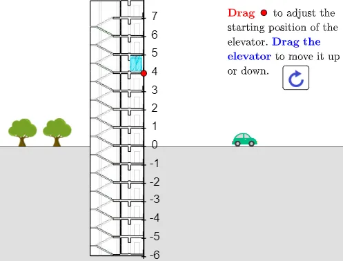
This example demonstrates the addition of directed numbers using an elevator model. It involves core mathematical concepts such as directed numbers, addition operations, and real-world applications. Construction highlights include GeoGebra commands/objects like Intersect (intersection), Point (point), CircleArc (arc), Sequence (sequence), PathParameter (path parameter), Corner (corner), Polygon (polygon), Vector (vector), and Segment (segment). Suitable for middle school students to understand the practical meaning of abstract mathematical concepts in directed number addition.
GeoGebra Commands & Parameters
Intersect(xAxis, yAxis) → OPoint(yAxis) → CPoint(xAxis) → BCircleArc(O, B, C) → cPoint(c) → ASequence(Translate[O, Vector[(i * UnitVector[Vector[O, A]])]], i, -6, 7) → l1Sequence(Translate[O, Vector[((0.1 * i) * UnitVector[Vector[O, A]])]], i, -200, 200) → l3Point(l1) → PPathParameter(A) → tPathParameter(P) → aCorner(5) → DimenPoint(Ray[D + (0, 1), D + (0, 2)]) → FPolygon((x(Corner[2]), 0), (x(Corner[1]), 0), Corner[1], Corner[2]) → q1, g, h, i, jSequence(Text[i, Translate[O, (-0.2, -0.7) + (t * (0.5, 0.6)) + If[i ≥ 0, (0.1, 0), (0, 0)] + (i * UnitVector[Vector[O, A]])]], i, -6, 7) → l2Vector(P + (1.5, 0), Q) → uSegment((0, 8), (0, -6)) → fPolygon(T, U, U + (0, 1), T + (0, 1)) → q2, t_1, u_1, k, lSegment(Q - (0.25, 0), Q + (0.25, 0)) → mSegment(V - (0.25, 0), V + (0.25, 0)) → nSegment(V - (0.25, 0), P) → pSegment(Q - (0.25, 0), T) → q
AI Drawing Prompt Reference
Draw an elevator model to demonstrate addition of directed numbers. Start with coordinate axes and an origin. Create a circular arc connecting points on the x-axis and y-axis, and place a point on the arc to define a direction. Generate a series of equally spaced translated points along this direction to form tick marks, with integer labels. Select a point on the tick marks as the elevator position, and use an arrow vector to show movement. Add a vertical line as the elevator shaft, with rectangular sliders and connecting segments on both sides to simulate up-and-down motion. The final graphic includes axes, arc, tick marks, number labels, arrow, and elevator structure.
The prompt above was compiled from the original drawing commands and is for reference only.