
Cylinder Sections Exploration
Loading the math board and drawing, please wait…
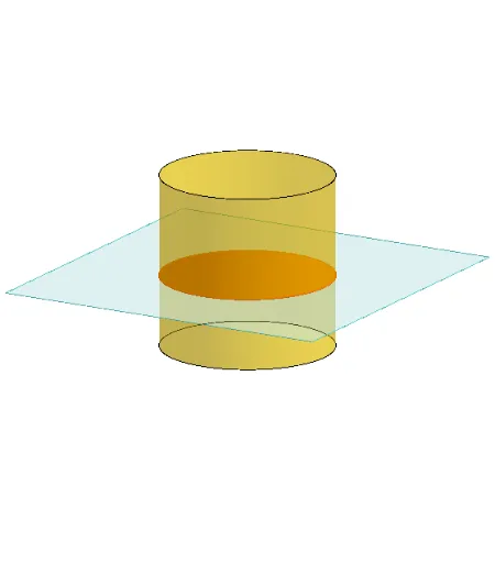
This example demonstrates how different cross-section shapes of a cylinder can be generated by altering the section angle and position. Core math concepts include solid geometry, angle transformation, and spatial geometric relationships. Construction highlights the use of GeoGebra commands/objects like Polygon, PointIn, Translate, Rotate, Cylinder, Plane, IntersectPath, OrthogonalLine, and Ends. Suitable for high school geometry teaching and construction exploration.
GeoGebra Commands & Parameters
Polygon(B + (-2, -2), B + (2, -2), B + (2, 2), B + (-2, 2)) → poly3, e, f, g, iPointIn(poly3) → CTranslate((0, 0, 0), Vector[B, C]) → APolygon(A + (-4, -4), A + (4, -4), A + (4, 4), A + (-4, 4)) → poly1, a, b, c, dRotate(Rotate[Translate[poly1, Vector[A, A + (0, 0, h)]], (90° * s), A + (0, 0, h), yAxis], (90° * t), A, zAxis) → poly2Rotate(D, 120°, (0, 0, 0)) → EPolygon(D, E, 3, xOyPlane) → poly4, j, k, l, FCylinder((0, 0, 0), (0, 0, 4), 2) → m, e_1, f_1, oPointIn(poly2) → GPointIn(poly2) → HPointIn(poly2) → IPlane(G, I, H) → nIntersectPath(n, m) → poly6OrthogonalLine(A, n) → d_1Ends(m) → g_1, g_1_1
AI Drawing Prompt Reference
Draw a cylinder and show how different cross-section shapes can be generated by altering the section angle and position. First, draw a rectangle and rotate it, then place it on the cylinder to find the intersection line between the section and the cylinder. Also, draw a line perpendicular to the base of the cylinder and display the intersection line with the section. These operations demonstrate the changes in cross-section shapes and their relationship with the cylinder.
The prompt above was compiled from the original drawing commands and is for reference only.