
Cube Vertices and Sphere: Visualizing the 8 Corner Points
Loading the math board and drawing, please wait…
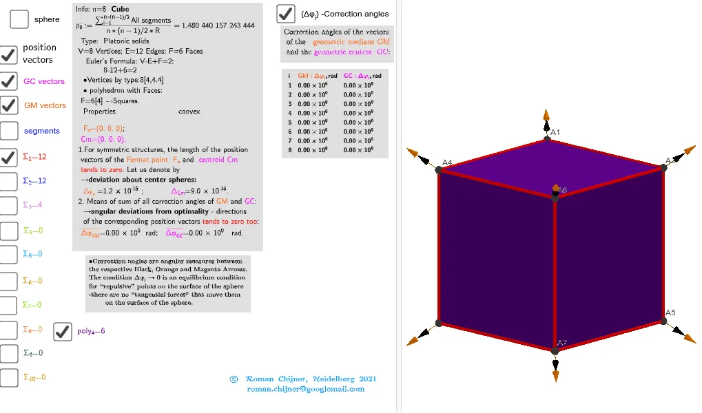
This example demonstrates a 3D solid-geometry visualization of a cube together with a related sphere, highlighting the arrangement and geometric relationships of the cube’s eight vertices in space. It centers on key concepts such as solid geometry, the cube’s vertex structure (8 corner points), and the definition of a sphere (center and radius) to represent a spatial constraint or reference. Construction highlights: Sphere is used to create the sphere; TableText and Text are used to display labels and vertex-related information; UnicodeToLetter helps build readable symbolic annotations; Sum supports parameter or coordinate computations; and Segments plus connected geometric objects are used to render the cube’s edges and vertex connections. Suitable for upper secondary to early university levels, especially for lessons on 3D geometry, coordinate/space visualization, and geometric modeling with GeoGebra.
GeoGebra Commands & Parameters
UnicodeToLetter(34) → u34Text("" + Um1) → txt_pSum(Flatten[Sequence[Append[Sequence[Element[txt_p, i], i, m01(k), m02(k)], " "], k, 1, 5]]) → txtUm1Zip(Vector[a, a + UnitVector[a]], a, Points00) → lVector1Zip(Vector[a, a + (1.5 * UnitVector[b])], a, Points00, b, Wi_Pc) → lVector2Zip(Vector[a, a + (1.5 * UnitVector[b])], a, Points00, b, Wi_P) → lVector3Sphere((0, 0, 0), 5) → sphTableText(Append["i", 1…n], Append[" \fgcolor{orange}{GM :Δφ_i}, rad", l1w], Append["\fgcolor{magenta}{GC :Δφ_i} , rad", l1cw], "v") → text23rZip(Segment[Element[Points00, y(a)], Element[Points00, z(a)]], a, ll1bb(1)) → ll1Zip(Segment[Element[Points00, y(a)], Element[Points00, z(a)]], a, ll1bb(2)) → ll2Zip(Segment[Element[Points00, y(a)], Element[Points00, z(a)]], a, ll1bb(3)) → ll3
AI Drawing Prompt Reference
Create a 3D visualization of a cube with its eight vertices clearly marked, accompanied by a sphere centered at the origin with radius 5. Connect the cube's edges with line segments, and add vector arrows at each vertex to indicate directions. Include a table nearby showing angular values related to the vertices, and use text labels for vertex symbols. Emphasize the spatial relationship between the cube's vertices and the sphere, illustrating how the vertices lie on or relate to the spherical surface.
The prompt above was compiled from the original drawing commands and is for reference only.