
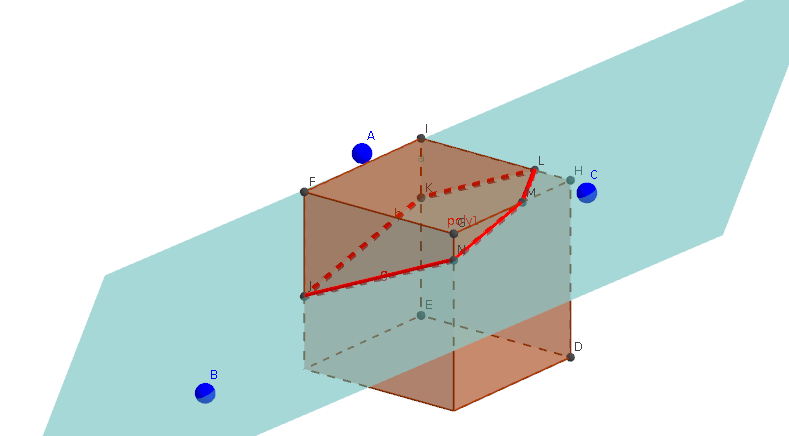
Cube Section Plan Diagram
Loading the math board and drawing, please wait…
In collections
intersection: surface-surface, curve-curve
intersection: surface-surface, curve-curve
intersection: surface-surface, curve-curve
intersection: surface-surface, curve-curve
This example demonstrates the cross-sectional shapes of a cube when intersected by different planes. It involves core math concepts like solid geometry, cross-section analysis, and polygon properties. Construction highlights include using Plane, Cube, and IntersectPath commands with objects like A, B, C, face1, faceDEIH. Suitable for high school geometry teaching or construction practice.
GeoGebra Commands & Parameters
Plane(A, B, C) → aCube((0, 0, 0), (1, 0, 0), xOyPlane) → b, D, face4, faceDEIH, faceFGHI, arête2, arête1, arête4, arêteDE, arête3, arêteEI, arêteFI, E, arêteFG, arête5, arêteGH, arêteDH, arêteHI, F, G, H, I, face1, face3, face2IntersectPath(a, b) → poly1, J, g, K, L, M, N, c, d, e, f
AI Drawing Prompt Reference
Draw a diagram showing the cross-sectional shapes of a cube intersected by different planes. The cube is positioned in a coordinate system with its base at the origin and top at (1,0,0), parallel to the xOy plane. Define a plane using three non-collinear points and calculate its intersection with the cube to form the cross-sectional polygon. The final image should include the cube's edges, faces, and the cross-sectional polygon, clearly illustrating the geometric relationships.
The prompt above was compiled from the original drawing commands and is for reference only.