
Cube Cross-Section Explorer
Loading the math board and drawing, please wait…
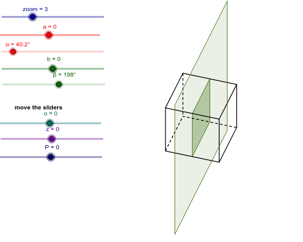
This GeoGebra example demonstrates the dynamic cross-sections formed when a plane intersects a cube, showing how the resulting polygon changes as the cutting plane moves and rotates. It covers core concepts in solid geometry, including polyhedron sections, plane-solid incidence, 3D vector dot products for coplanarity and perpendicularity, and ordered polygon construction. The construction relies on GeoGebra commands such as Odcinek_3D (3D segment), Element, Polygon, IloczynSkalarny3D (3D dot product), If, RemoveUndefined, Sequence, and Sort, together with points A1–C8, A, D1, D2, vectors v, w, u, and parameters a, b, zoom, α, β, z, δ, o, γ, r to generate intersection points and section boundaries. Suitable for high school solid geometry, university analytic geometry, and GeoGebra 3D modeling enthusiasts studying dynamic plane sections of cubes.
GeoGebra Commands & Parameters
Odcinek_3D(D1, D5, D4, D2) → c, dOdcinek_3D(D1, D2, D5, D4) → e, fOdcinek_3D(D1, D4, D2, D5) → g, hOdcinek_3D(D2, D6, D1, D3) → i, jOdcinek_3D(D2, D3, D6, D1) → k, lOdcinek_3D(D3, D7, D2, D4) → m, nOdcinek_3D(D3, D4, D7, D2) → p, qOdcinek_3D(D4, D8, D3, D1) → s, tOdcinek_3D(D8, D5, D7, D4) → a_1, b_1Odcinek_3D(D8, D7, D4, D5) → c_1, d_1Odcinek_3D(D7, D6, D3, D8) → e_1, f_1Odcinek_3D(D6, D5, D2, D7) → g_1, h_1Element(Join[B10], 1) → C10Element(Join[B10], 2) → D10Element(Join[B10], 3) → E10Element(Join[B11], 1) → C11Element(Join[B11], 2) → D11Element(Join[B11], 3) → E11Element(Join[B12], 1) → C12Element(Join[B12], 2) → D12Element(Join[B12], 3) → E12Element(Join[B13], 1) → C13Element(Join[B13], 2) → D13Element(Join[B13], 3) → E13Element(Join[B14], 1) → C14Element(Join[B14], 2) → D14Element(Join[B14], 3) → E14Polygon(F12, F13, F10, F11) → poly1, f12, f13, f10, f11IloczynSkalarny3D(B14, B15) → C15IloczynSkalarny3D(B15, C17) → E17IloczynSkalarny3D(B15, C18) → E18IloczynSkalarny3D(B15, C19) → E19IloczynSkalarny3D(B15, C20) → E20IloczynSkalarny3D(B15, C21) → E21IloczynSkalarny3D(B15, C22) → E22IloczynSkalarny3D(B15, C23) → E23IloczynSkalarny3D(B15, C24) → E24IloczynSkalarny3D(B15, C25) → E25IloczynSkalarny3D(B15, C26) → E26IloczynSkalarny3D(B15, C27) → E27IloczynSkalarny3D(B15, C28) → E28If((F17 ≥ 0) ∧ (F17 ≤ 1), F17) → G17If((F18 ≥ 0) ∧ (F18 ≤ 1), F18) → G18If((F19 ≥ 0) ∧ (F19 ≤ 1), F19) → G19If((F20 ≥ 0) ∧ (F20 ≤ 1), F20) → G20If((F21 ≥ 0) ∧ (F21 ≤ 1), F21) → G21If((F22 ≥ 0) ∧ (F22 ≤ 1), F22) → G22If((F23 ≥ 0) ∧ (F23 ≤ 1), F23) → G23If((F24 ≥ 0) ∧ (F24 ≤ 1), F24) → G24If((F25 ≥ 0) ∧ (F25 ≤ 1), F25) → G25If((F26 ≥ 0) ∧ (F26 ≤ 1), F26) → G26If((F27 ≥ 0) ∧ (F27 ≤ 1), F27) → G27If((F28 ≥ 0) ∧ (F28 ≤ 1), F28) → G28RemoveUndefined(list1) → list2Sequence(Angle[Element[list2, 1], F14, Element[list2, i]], i, 1, Length[list2]) → list3Sort(list3) → list4Sequence(Sequence[If[Element[list3, j] ≟ Element[list4, i], Element[list2, j]], j, 1, Length[list2]], i, 1, Length[list4]) → list5RemoveUndefined(Join[list5]) → list6Polygon(list6) → wielokąt1, , , ,
AI Drawing Prompt Reference
Draw a cube and show how the cross-section polygon changes as a plane intersects it. Start by drawing the 8 vertices of the cube, then draw the 12 edges. Define a plane and adjust its position and angle to observe the changes in the cross-section polygon. Finally, based on the intersection points of the plane and the cube, draw the cross-section polygon.
The prompt above was compiled from the original drawing commands and is for reference only.