
Cross Sections of Rectangular Prisms
Loading the math board and drawing, please wait…
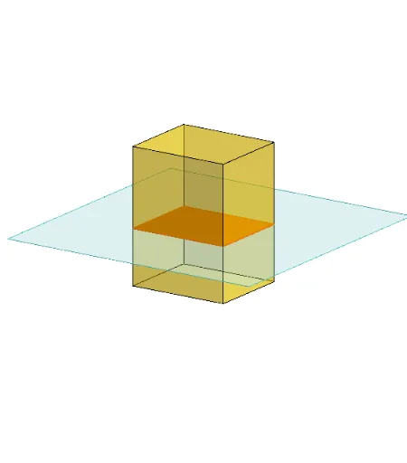
This example demonstrates how changing the orientation and position of cross-sections reveals the shapes formed within a rectangular prism (cuboid). Key math concepts include geometric cross-sections, spatial geometry relationships, and polygonal properties. GeoGebra commands and objects used in construction are Polygon, PointIn, Translate, Rotate, Prism, Plane, IntersectPath, OrthogonalLine. Suitable for high school students learning solid geometry, spatial reasoning, and geometric constructions.
GeoGebra Commands & Parameters
Polygon(B + (-2, -2), B + (2, -2), B + (2, 2), B + (-2, 2)) → poly3, e, f, g, iPointIn(poly3) → CTranslate((0, 0, 0), Vector[B, C]) → APolygon(A + (-4, -4), A + (4, -4), A + (4, 4), A + (-4, 4)) → poly1, a, b, c, dRotate(Rotate[Translate[poly1, Vector[A, A + (0, 0, h)]], (90° * s), A + (0, 0, h), yAxis], (90° * t), A, zAxis) → poly2Rotate(D, 120°, (0, 0, 0)) → EPrism(Polygon[(-1.5, -1.25, 0), (1.5, -1.25, 0), (1.5, 1.25, 0), (-1.5, 1.25, 0)], (-1.5, -1.25, 4)) → m, M, edge2, edge3, edge4, edge5, edge6, edge7, edge8, N, Q, face1, face2, face3, face4, face5, edge1Polygon(D, E, 3, xOyPlane) → poly4, j, k, l, FPointIn(poly2) → GPointIn(poly2) → HPointIn(poly2) → IPlane(G, I, H) → nIntersectPath(n, m) → poly6, poly5, r, a_1, b_1, c_1, K, L_1, O, P, J, L, p, qRotate(m, 0, zAxis) → m'Rotate(m, 0, zAxis) → m'_1OrthogonalLine(A, n) → d_1
AI Drawing Prompt Reference
Create a rectangular prism and draw a plane that slices through it, revealing the resulting polygonal cross‑section. Include a few reference rectangles and interior points to indicate where the cutting plane is positioned and how it is oriented. Show the intersection of the plane with the prism as a polygon, and add a line perpendicular from a reference point to the plane to illustrate the spatial relationship. The construction should display the solid, the cutting plane, the cross‑section shape, and the auxiliary geometry that helps visualize how the orientation and placement of the plane affect the section.
The prompt above was compiled from the original drawing commands and is for reference only.