
Components of a Vector: Orthogonal Decomposition Visualization
Loading the math board and drawing, please wait…
In collections
Vectors - Simmons
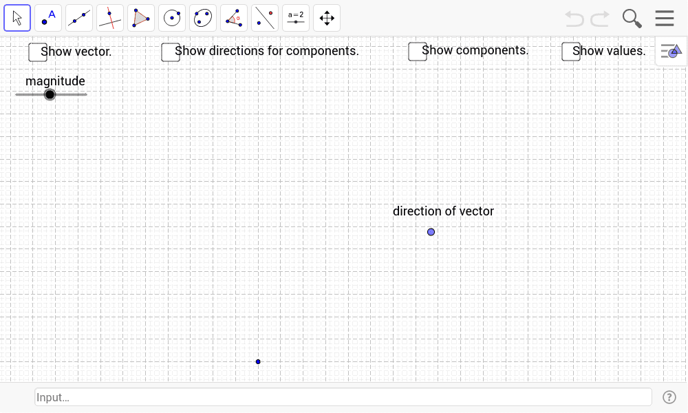
This GeoGebra example dynamically demonstrates the decomposition of a plane vector into its orthogonal components, showing how a vector is formed by its horizontal and vertical parts. The core mathematical concepts include vector addition, orthogonal decomposition, magnitude (length), direction angle, and trigonometric relationships (cosθ and sinθ). Construction highlights: using commands such as Line, Circle, Point, OrthogonalLine, Intersect, Angle, Vector, Length, Segment, and Midpoint to build the vector and its projections, with checkboxes (check_1 to check_4) to toggle visibility of components, angle labels, and text annotations for interactive exploration. Suitable for high school or early college students learning vector basics, analytic geometry, or physics force decomposition, and for teachers to illustrate the relationship between vector components and coordinate axes.
GeoGebra Commands & Parameters
Line(A, direction) → aCircle(A, magnitude) → cPoint(c) → BOrthogonalLine(B, a) → eIntersect(a, e) → EAngle(E, A, B) → θVector(A, E) → wLength(w) → component_1Vector(A, B) → uOrthogonalLine(A, a) → bOrthogonalLine(B, b) → dIntersect(b, d) → DVector(A, D) → vSegment(D, B) → fSegment(E, B) → gLength(v) → component_2Midpoint(A, B) → CSegment(A, B) → h
AI Drawing Prompt Reference
Draw a vector decomposition diagram on a plane, including vector w with its horizontal component u and vertical component v, and their projections on the coordinate axes with their lengths. Start by drawing a direction line a through point A, then draw a circle c with A as the center and the length of vector w as the radius. Take point B on the circle, draw a line e through B that is perpendicular to a, and find the intersection point E. Draw vector w from A to E, and calculate its length component_1. Draw a line b through A that is perpendicular to a, and draw a line d through B that is perpendicular to b, and find the intersection point D. Draw vector v from A to D, and calculate its length component_2. Finally, draw line segment h from A to B, and draw line segments f and g as the projections of vector v on the coordinate axes.
The prompt above was compiled from the original drawing commands and is for reference only.