
Bezier Surface Construction Example
Loading the math board and drawing, please wait…
In collections
intersection: surface-surface, curve-curve
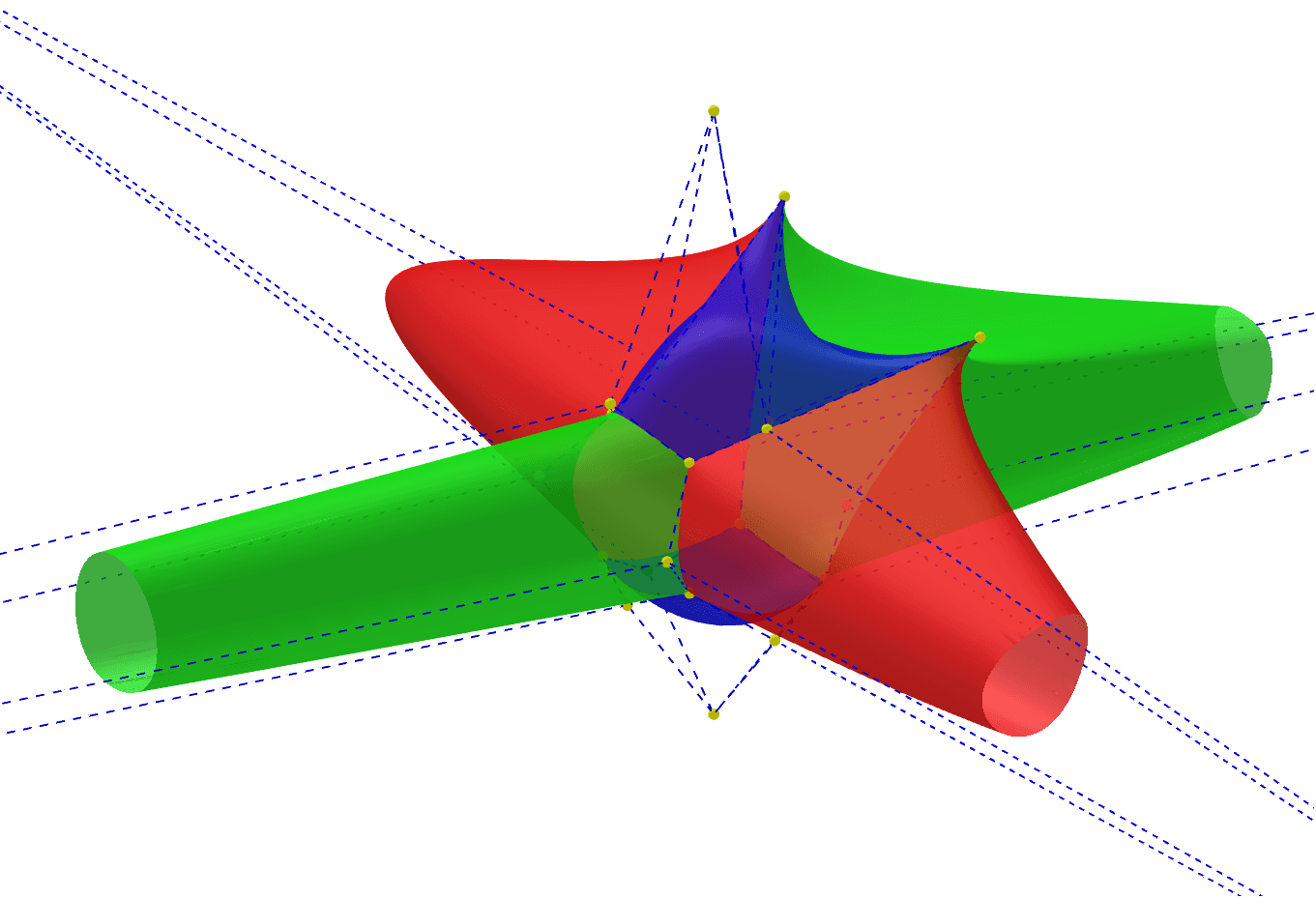
This example demonstrates constructing a solid using Bezier surfaces of degree 2. Key mathematical concepts include Bezier surfaces, plane intersections, and geometric transformations. Construction involves GeoGebra commands such as Cube, Line, Intersect, Plane, OrthogonalLine, Point, Bezier2, and IntersectPath. Suitable for high school students or college freshmen learning solid geometry and parametric curve drawing.
GeoGebra Commands & Parameters
Cube(A, B, xOyPlane) → a, C, powierzchniaBCGF, powierzchniaCDHG, powierzchniaEFGH, krawędźAD, krawędźAB, krawędźBC, krawędźCD, krawędźAE, krawędźDH, krawędźEH, D, krawędźEF, krawędźBF, krawędźFG, krawędźCG, krawędźGH, E, F, G, H, powierzchniaABCD, powierzchniaADHE, powierzchniaABFELine(A, G) → bLine(E, C) → cLine(F, D) → dLine(H, B) → eIntersect(c, xOyPlane) → IPlane(F, E, I) → fIntersect(d, c) → JPlane(H, G, J) → gPlane(H, E, J) → hPlane(F, J, G) → iOrthogonalLine(J, f) → jOrthogonalLine(J, g) → kOrthogonalLine(J, i) → lOrthogonalLine(J, krawędźFG, space) → mPoint(d) → KPoint(k) → LPoint(c) → MPoint(m) → NPoint(l) → OPoint(b) → PPoint(j) → QPoint(e) → ROrthogonalLine(J, g) → nOrthogonalLine(J, xOyPlane) → pPoint(p) → SPłatProstokątnyBezier2(K, L, M, N, S, O, P, Q, R) → q, r, g_1, h_1, o, s, t, a_1, b_1, c_1, d_1, e_1, f_1IntersectPath(i, h) → i_1OrthogonalLine(J, krawędźCG, space) → j_1OrthogonalLine(J, krawędźDH, space) → k_1Point(j_1) → TPoint(i_1) → UPoint(k_1) → VPoint(c) → WPoint(k) → ZPoint(d) → A_1PłatProstokątnyBezier2(P, Q, R, T, U, V, W, Z, A_1) → l_1, m_1, c_2, d_2, u, n_1, p_1, q_1, r_1, s_1, t_1, a_2, b_2IntersectPath(f, g) → e_2Point(e_2) → B_1Point(j_1) → C_1Point(m) → D_1Point(b) → E_1PłatProstokątnyBezier2(R, O, M, V, B_1, C_1, A_1, D_1, E_1) → f_2, g_2, q_2, r_2, v, h_2, i_2, j_2, k_2, l_2, m_2, n_2, p_2Point(i_1) → F_1Point(k_1) → G_1Point(j) → H_1Point(e) → I_1PłatProstokątnyBezier2(M, L, K, C_1, F_1, G_1, E_1, H_1, I_1) → s_2, t_2, i_3, j_3, w, a_3, b_3, c_3, d_3, e_3, f_3, g_3, h_3Point(l) → J_1Point(e_2) → K_1PłatProstokątnyBezier2(K, N, P, G_1, K_1, T, I_1, J_1, W) → k_3, l_3, b_4, c_4, o_1, m_3, n_3, p_3, q_3, r_3, s_3, t_3, a_4Point(p) → L_1PłatProstokątnyBezier2(W, Z, A_1, J_1, L_1, D_1, I_1, H_1, E_1) → d_4, e_4, n_4, p_4, u_1, f_4, g_4, h_4, i_4, j_4, k_4, l_4, m_4
AI Drawing Prompt Reference
This graphic is a complex solid constructed using Bezier surfaces. It begins with a cube, defines several line segments and planes, and computes their intersections to obtain points. Then, perpendicular lines are constructed from these points, and more points are obtained by intersecting these lines with planes. Finally, a Bezier surface construction function is used to combine these points into multiple surface patches, which together form a continuous surface structure. The surface patches may join to create an overall solid, demonstrating the application of Bezier surfaces in geometric construction.
The prompt above was compiled from the original drawing commands and is for reference only.