
Alternate Exterior Angles: Interactive Parallel Line Investigation
Loading the math board and drawing, please wait…
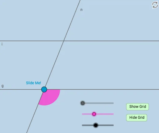
This example demonstrates the relationship between alternate exterior angles formed when a transversal intersects parallel lines. Key math concepts include properties of parallel lines, transversals, corresponding angles, alternate interior angles, and the definition of alternate exterior angles. It is constructed using GeoGebra commands/objects like Point, Line, Rotate, Angle, Circle, Intersect, Segment, Vector, Ray, CircleArc, CircleSector, and Translate. Suitable for high school students to understand the geometric properties of parallel lines and transversals, and the constant relationship of alternate exterior angles.
GeoGebra Commands & Parameters
Point(y = 0) → ALine(A, B) → fRotate(B, α, A) → B'Angle(B, A, B') → γLine(A, B') → gRotate(B', β, A) → B''Angle(B', A, B'') → δLine(A, B'') → hCircle(A, a) → cIntersect(c, h, 2) → CLine(C, g) → iCircle(C, A) → dCircle(A, C) → eIntersect(e, h, 2) → JSegment(A, C) → jCircle(A, (0.3 * j)) → kCircle(C, (0.3 * j)) → pIntersect(p, h) → N, OIntersect(k, h) → P, QIntersect(k, g) → T, UIntersect(p, i, 2) → VIntersect(p, i, 1) → WCircle(C, j / 2) → g_1Circle(A, j / 2) → h_1Intersect(g_1, i, 2) → DIntersect(g_1, i, 1) → EIntersect(g_1, h, 2) → HIntersect(g_1, h) → I, ZIntersect(h_1, h) → A_1, B_1Intersect(h_1, g) → E_1, F_1Point(j) → G_1Vector(A, G_1) → uSegment(A, G_1) → lRay(A, A_1) → mRay(C, H) → nVector(A, G_1) → vSegment(G_1, C) → sCircleArc(C, N, O) → rPoint(r) → FRotate(F, (-δ), C) → F'Angle(F', C, F) → εSegment(A, C) → bCircleSector(A, P, U) → d_1Translate(d_1, v) → e_1CircleArc(C, W, V) → f_1Point(f_1) → GRotate(G, (-(π - ε)), C) → G'Angle(G', C, G) → ζCircleSector(C, G', G) → k_1CircleArc(A, P, U) → qSegment(A, C) → t
AI Drawing Prompt Reference
Draw two parallel lines and a transversal line through them to mark a pair of alternate exterior angles. Then, rotate these lines and angles around one point to create another pair of alternate exterior angles and label their measures. Finally, use circles and arcs to connect these points and form the geometric figure.
The prompt above was compiled from the original drawing commands and is for reference only.