
3D Moment Demonstration
Loading the math board and drawing, please wait…
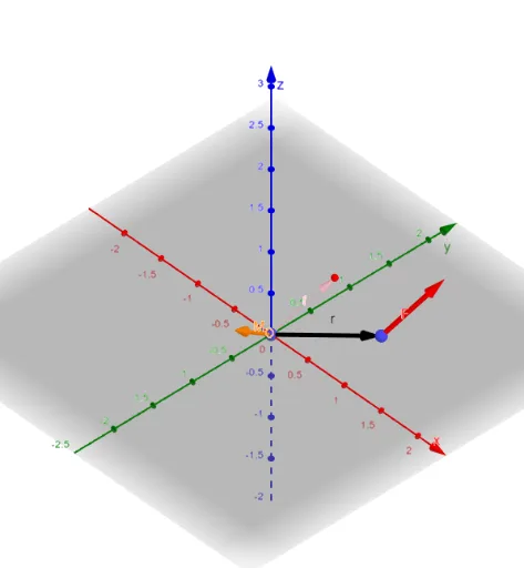
This example demonstrates the calculation and visualization of moments in 3D space. It involves core math concepts like moment, vector, polygon, coordinate geometry, and calculus. Construction highlights include using commands like Vector, Polygon, Line, Angle, Length in GeoGebra, with sliders for dynamic parameter adjustment. Suitable for high school students and teachers in solid geometry, vector, and calculus education.
GeoGebra Commands & Parameters
Vector(A) → fVector(C) → rVector(C, B) → FPolygon(O, C, B, A) → q1, o, c, b, aLine(O, C) → gAngle(g, c) → θLength(F) → LFLength(r) → LrLength(M_O) → LMVector(Y0, Y0 + (xr, 0, 0)) → rxyVector(Z0, Z0 + (xr, 0, 0)) → rxzVector(Z0, Z0 + (0, yr, 0)) → ryzVector(X0, X0 + (0, yr, 0)) → ryxVector(X0, X0 + (0, 0, zr)) → rzxVector(Y0, Y0 + (0, 0, zr)) → rzyVector(D, D + (xF, 0, 0)) → fxVector(E, E + (0, yF, 0)) → fyVector(G, G + (0, 0, zF)) → fz
AI Drawing Prompt Reference
Create a 3D moment demonstration. Start by setting up a coordinate system and defining points O, A, B, C, D, E, F, and G. Use the Vector command to create vectors f, r, F, q1, g, rxy, rxz, ryz, ryx, rzx, rzy, fx, fy, and fz. Adjust sliders to dynamically change parameters and show the calculation and visualization of moments.
The prompt above was compiled from the original drawing commands and is for reference only.