
LMOrigami22 腰带立方体
几何画板及绘图内容加载中,请稍等……
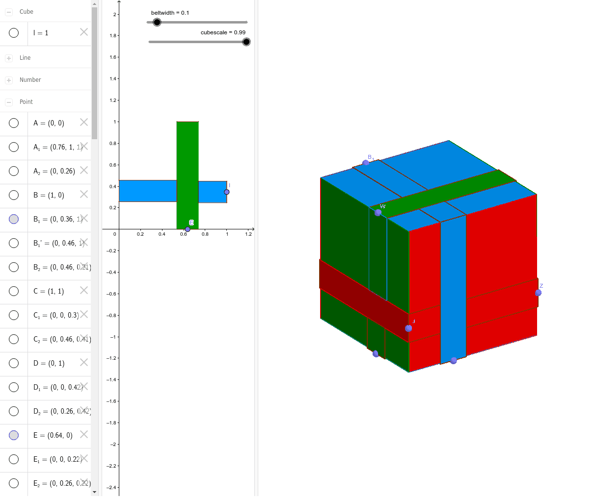
这个范例演示了一个由点、多边形和立方体构成的腰带立方体图形。涉及的核心数学概念包括立体几何、对称性和几何作图。作图要点包括使用 GeoGebra 命令如 Point(点)、Intersect(交点)、Polygon(多边形)、OrthogonalLine(垂线)、Mirror(镜像)、Cube(立方体)、Line(直线)、Dilate(缩放);对象包括 beltwidth(腰带宽度)、C, D, A, B, poly1, a, b, c, d, E, e, F, f, G, H, F', H', poly2, f', f_1, h, h', I, J, g, i, K, K', J', poly3, k, j, j', k', L, l, O, P, Q。适合高中及以上学段学习立体几何和几何作图。
GeoGebra 命令及参数
Point(yAxis) → DIntersect(xAxis, yAxis) → APoint(xAxis) → BPolygon(A, B, C, D) → poly1, a, b, c, dPoint(a) → EOrthogonalLine(E, a) → eOrthogonalLine(F, a) → fIntersect(e, c) → GIntersect(f, c) → HMirror(F, e) → F'Mirror(H, e) → H'Polygon(F', F, H, H') → poly2, f', f_1, h, h'Point(b) → IOrthogonalLine(I, b) → gOrthogonalLine(J, b) → iIntersect(i, f_1) → KMirror(K, g) → K'Mirror(J, g) → J'Polygon(K, J, J', K') → poly3, k, j, j', k'Intersect(d, yAxis) → LCube(B, C, poly1) → l, O, faceCOSR, faceOPTS, faceQRST, edgeBP, edgeBC, edgeCO, edgeOP, edgeBQ, edgePT, edgeQT, P, edgeQR, edgeCR, edgeRS, edgeOS, edgeST, Q, R, S, T, faceBCOP, faceBPTQ, faceBCRQPoint(edgeBQ) → UPoint(edgeQT) → WPoint(edgeCR) → ZPoint(edgeST) → B_1Point(edgePT) → C_1OrthogonalLine(U, edgeBQ, faceBPTQ) → pMirror(U', p) → U''OrthogonalLine(U', edgeBQ, faceBPTQ) → qOrthogonalLine(U'', edgeBQ, faceBPTQ) → rIntersect(q, edgePT) → D_1Intersect(edgePT, r) → E_1Polygon(E_1, U'', U', D_1) → poly5, e_1, u'', u', d_1OrthogonalLine(J', b, faceBCRQ) → sOrthogonalLine(J, b, faceBCRQ) → tIntersect(t, edgeQR) → F_1Intersect(s, edgeQR) → G_1Polygon(G_1, F_1, J, J') → poly6, g_1, f_2, j_1, j'_1OrthogonalLine(U', edgeBQ, faceBCRQ) → mOrthogonalLine(U'', edgeBQ, faceBCRQ) → nIntersect(m, j'_1) → MIntersect(n, j'_1) → NPolygon(U'', N, M, U') → poly4, u''_1, n_1, m_1, u'_1OrthogonalLine(W, edgeQT, faceQRST) → a_1Mirror(W', a_1) → W''OrthogonalLine(W'', edgeQT, faceQRST) → b_1OrthogonalLine(W', edgeQT, faceQRST) → c_1Intersect(b_1, edgeRS) → VIntersect(c_1, edgeRS) → A_1Polygon(V, A_1, W', W'') → poly7, v, a_2, w', w''OrthogonalLine(W'', edgeQT, faceBPTQ) → h_1OrthogonalLine(W', edgeQT, faceBPTQ) → i_1OrthogonalLine(F, a, faceBPTQ) → k_1OrthogonalLine(F', a, faceBPTQ) → l_1Intersect(e_1, l_1) → H_1Intersect(k_1, e_1) → I_1Intersect(i_1, u') → J_1Intersect(h_1, u') → K_1Polygon(W'', K_1, J_1, W') → poly8, w''_1, k_2, j_2, w'_1Polygon(F', F, I_1, H_1) → poly9, f'_1, f_3, i_2, h_2OrthogonalLine(F_1, edgeQR, faceQRST) → p_1OrthogonalLine(G_1, edgeQR, faceQRST) → q_1Intersect(p_1, a_2) → L_1Intersect(q_1, a_2) → M_1Polygon(M_1, G_1, F_1, L_1) → poly10, m_2, g_2, f_4, l_2OrthogonalLine(Z, edgeCR, faceCOSR) → r_1Mirror(Z', r_1) → Z''OrthogonalLine(Z', edgeCR, faceCOSR) → s_1OrthogonalLine(Z'', edgeCR, faceCOSR) → t_1Intersect(s_1, edgeOS) → N_1Intersect(t_1, edgeOS) → O_1Polygon(Z'', O_1, N_1, Z') → poly11, z'', o_1, n_2, z'OrthogonalLine(A_1, edgeRS, faceCOSR) → b_2OrthogonalLine(V, edgeRS, faceCOSR) → c_2OrthogonalLine(H, c, faceCOSR) → d_2OrthogonalLine(H', c, faceCOSR) → e_2Intersect(t_1, d_2) → P_1Intersect(t_1, e_2) → Q_1Intersect(c_2, s_1) → R_1Intersect(s_1, b_2) → S_1Polygon(S_1, R_1, V, A_1) → poly12, s_2, r_2, v_1, a_3Polygon(H, H', Q_1, P_1) → poly13, h_3, h'_1, q_2, p_2OrthogonalLine(Z', edgeCR, faceBCRQ) → t_2OrthogonalLine(Z'', edgeCR, faceBCRQ) → b_3Intersect(t_2, f_2) → T_1Intersect(b_3, f_2) → U_1Polygon(U_1, Z'', Z', T_1) → poly14, u_1, z''_1, z'_1, t_3OrthogonalLine(B_1, edgeST, faceOPTS) → c_3OrthogonalLine(B_1', edgeST, faceOPTS) → d_3Mirror(B_1', c_3) → V_1OrthogonalLine(V_1, edgeST, faceOPTS) → e_3Intersect(d_3, d) → W_1Intersect(d, edgeOP) → Z_1Intersect(e_3, d) → A_2Polygon(W_1, A_2, V_1, B_1') → poly15, w_1, a_4, v_2, b_1'OrthogonalLine(O_1, edgeOS, faceOPTS) → g_3OrthogonalLine(N_1, edgeOS, faceOPTS) → i_3OrthogonalLine(E_1, edgePT, faceOPTS) → j_3OrthogonalLine(D_1, edgePT, faceOPTS) → k_3Intersect(d_3, g_3) → B_2Intersect(i_3, d_3) → C_2Intersect(e_3, k_3) → D_2Intersect(e_3, j_3) → E_2Polygon(O_1, B_2, C_2, N_1) → poly16, o_2, b_4, c_4, n_3Polygon(E_1, E_2, D_2, D_1) → poly17, e_4, e_5, d_4, d_5OrthogonalLine(B_1', edgeST, faceQRST) → l_3OrthogonalLine(V_1, edgeST, faceQRST) → m_3Intersect(l_3, w'') → F_2Intersect(m_3, w'') → G_2Polygon(B_1', V_1, G_2, F_2) → poly18, b_5, v_3, g_4, f_5OrthogonalLine(W_1, d, xOyPlane) → p_3OrthogonalLine(A_2, d, xOyPlane) → q_3Intersect(p_3, h') → H_2Intersect(q_3, h') → I_2Polygon(W_1, H_2, I_2, A_2) → poly19, w_2, h_4, i_4, a_5Line(A, R) → r_3Line(T, C) → s_3Intersect(s_3, r_3) → J_2Dilate(faceBCOP, cubescale, J_2) → faceBCOP'Dilate(faceBCRQ, cubescale, J_2) → faceBCRQ'Dilate(faceBPTQ, cubescale, J_2) → faceBPTQ'Dilate(faceCOSR, cubescale, J_2) → faceCOSR'Dilate(faceOPTS, cubescale, J_2) → faceOPTS'Dilate(faceQRST, cubescale, J_2) → faceQRST'
AI 绘图提示语参考
画一个由点和多边形构成的带状立方体,展示立体几何和对称性。首先绘制一个四边形,然后从其顶点出发,通过正交线和镜像操作创建多个几何形状,包括立方体和多个多边形。最后将这些形状组合起来,形成一个复杂的立体结构,强调几何构造的过程和对称性。
以上提示语为根据原始绘图命令整理而来,仅供参考。