
艺术螺旋线
几何画板及绘图内容加载中,请稍等……
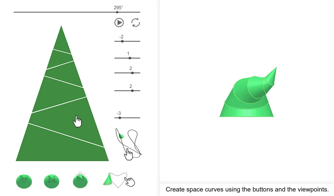
这个范例展示了艺术螺旋线的构造过程。它涉及圆、椭圆和旋转等核心数学概念。通过使用GeoGebra命令如Line、Sequence、Polygon、Intersect等,可以动态地构造出螺旋线的形状。适合高中及以上学生学习解析几何和参数方程。
GeoGebra 命令及参数
Line((0, 0, 0), (0, 0, 1)) → tSequence((XB((i * β)), YB((i * β)), ZB((i * β))), i, 0, n) → PontBPolygon(PontB) → Lap1Intersect(t, Line[A1, B2]) → MtDistance(Mt, A1) → maDistance(Mt, B2) → mbSequence((XC((i * β)), YC((i * β)), ZC((i * β))), i, 0, n) → PontCCircle((d, 0, 0), r, xOyPlane) → k0Line((0, 0, 0), (0, 1, 0)) → tyEllipse((0, fe), (0, (-fe)), ae) → e0Dilate(Translate[e0, Vector[(0, 0, c)]], dd, Mt) → alaplapRotate(k0, φ, ty) → kör1Rotate(kör1, 180°, t) → k1Dilate(k1, nm, Mt) → kör2Dilate(kör1, nm^(2), Mt) → kör3Dilate(kör2, nm^(2), Mt) → kör4Dilate(kör3, nm^(2), Mt) → kör5Dilate(PontB, nm^(2), Mt) → PontDCenter(kör1) → K1OrthogonalLine(K1, kör1) → f1Dilate(PontC, nm^(2), Mt) → PontEPolygon(PontC) → Lap2Dilate(PontD, nm^(2), Mt) → PontFPolygon(PontD) → Lap3Polygon(PontE) → Lap4Polygon(PontF) → Lap5Segment(A, Mt) → alkotóSequence((XA((i * β)), YA((i * β)), ZA((i * β))), i, 0, n) → PontAPolygon(PontA) → LapASequence(Polygon[Element[PontB, i], Element[PontA, i], Element[PontA, i + 1], Element[PontB, i + 1]], i, 1, n) → QASequence(Polygon[Element[PontC, i], Element[PontB, i], Element[PontB, i + 1], Element[PontC, i + 1]], i, 1, n) → Q1Sequence(Polygon[Element[PontD, i], Element[PontC, i], Element[PontC, i + 1], Element[PontD, i + 1]], i, 1, n) → Q2Sequence(Polygon[Element[PontF, i], Element[PontE, i], Element[PontE, i + 1], Element[PontF, i + 1]], i, 1, n) → Q4Sequence(Polygon[Element[PontF, i], Element[PontF, i + 1], Mt], i, 1, n) → QCCenter(kör2) → K2Center(kör3) → K3Center(kör4) → K4Center(kör5) → K5OrthogonalLine(K2, kör2) → f2OrthogonalLine(K3, kör3) → f3OrthogonalLine(K4, kör4) → f4OrthogonalLine(K5, kör5) → f5Rotate(Rotate[Rotate[Rotate[Rotate[Mt, (s5 * α), f5], (s4 * α), f4], (s3 * α), f3], (s2 * α), f2], (s1 * α), f1) → MRotate(Rotate[Rotate[Rotate[Rotate[kör5, (s5 * α), f5], (s4 * α), f4], (s3 * α), f3], (s2 * α), f2], (s1 * α), f1) → Fkör5Rotate(Rotate[Rotate[Rotate[kör4, (s4 * α), f4], (s3 * α), f3], (s2 * α), f2], (s1 * α), f1) → Fkör4Rotate(Rotate[Rotate[kör3, (s3 * α), f3], (s2 * α), f2], (s1 * α), f1) → Fkör3Rotate(Rotate[kör2, (s2 * α), f2], (s1 * α), f1) → Fkör2Rotate(Q1, (s1 * α), f1) → FQ1Rotate(Rotate[Rotate[Rotate[Rotate[QC, (s5 * α), f5], (s4 * α), f4], (s3 * α), f3], (s2 * α), f2], (s1 * α), f1) → FQCRotate(Rotate[Rotate[Rotate[Q4, (s4 * α), f4], (s3 * α), f3], (s2 * α), f2], (s1 * α), f1) → FQ4Rotate(Rotate[Q2, (s2 * α), f2], (s1 * α), f1) → FQ2Rotate(Rotate[Rotate[Rotate[Rotate[Lap5, (s5 * α), f5], (s4 * α), f4], (s3 * α), f3], (s2 * α), f2], (s1 * α), f1) → FLAP5Rotate(Rotate[Rotate[Rotate[Lap4, (s4 * α), f4], (s3 * α), f3], (s2 * α), f2], (s1 * α), f1) → FLAP4Rotate(Rotate[Rotate[Lap3, (s3 * α), f3], (s2 * α), f2], (s1 * α), f1) → FLAP3Rotate(Rotate[Lap2, (s2 * α), f2], (s1 * α), f1) → FLAP2If(Cs, Locus[M, α], NaN) → vmSequence(Polygon[Element[PontE, i], Element[PontD, i], Element[PontD, i + 1], Element[PontE, i + 1]], i, 1, n) → Q3Rotate(Rotate[Rotate[Q3, (s3 * α), f3], (s2 * α), f2], (s1 * α), f1) → FQ3If(n ≤ 12, (360°) / n, 5°) → dαPolygon(G, F, H) → t1, h, g, fPolygon(K, J, I, L) → q1, k, j, i, lPolygon(N, O, P, Q) → q2, n_1, o, p, qPolygon(R, S, T, U) → q3, r_1, s_1, t_1, uPolygon(V, E_1, D_1, C_1) → q4, v, e_1, d_1, c_1Polygon(B_1, A_1, Z, W) → q5, b_1, a_1, z_1, w
AI 绘图提示语参考
绘制一个艺术螺旋线,包含一系列椭圆和圆,通过旋转和缩放逐步构建。首先画一条直线,然后生成一系列点,形成螺旋线的基础。接着绘制一系列圆和椭圆,并通过旋转和缩放操作,使它们围绕中心点旋转并逐渐放大。最后,使用这些圆和椭圆构建多边形,形成螺旋线的外观。
以上提示语为根据原始绘图命令整理而来,仅供参考。