
四冲程发动机模拟
几何画板及绘图内容加载中,请稍等……
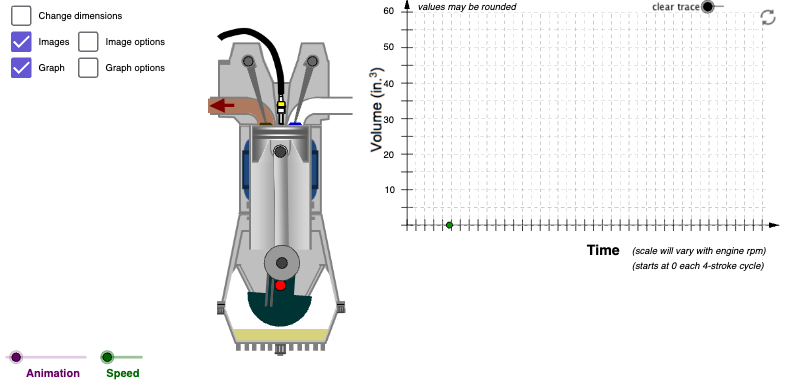
①本范例演示四冲程发动机工作循环中活塞位移与时间关系的图形模拟;②涉及核心数学概念包括函数图像、三角函数、几何作图、参数方程;③构造要点运用了Line, Circle, Intersect, Point, If, Angle, OrthogonalLine, Segment, Mirror, Polygon, Midpoint, Vector, Conic, CircleSector, Sequence等GeoGebra命令与对象;④适合高中及以上学生及工程技术人员学习发动机原理与数学建模。
GeoGebra 命令及参数
Line(Crankshaft, Crankshaft + (0, 10)) → VerticalCircle(Crankpin, (scaleFactor * rodLength)) → ConnectingRodCircleIntersect(ConnectingRodCircle, Vertical, 2) → WristpinLine(Crankpin, Crankshaft) → iPoint(i) → CounterBalCenterPtIf(angleNumAdj > 0 ∧ angleNumAdj < 0.1, ((-1 * 1.5) * angleNumAdj), If[angleNumAdj ≥ 0.1 ∧ angleNumAdj < 0.2, ((-1 * 1.5) * ((-angleNumAdj) + 0.2)), 0]) → valve1MotionVertAngle(CrankShaftRadius, Crankshaft, Rotate[CrankShaftRadius, α, Crankshaft]) → angleLine(Wristpin, Crankpin) → bOrthogonalLine(Crankpin, b) → cOrthogonalLine(Wristpin, b) → dCircle(Crankpin, 0.2) → rodbasecircledarkCircle(Wristpin, 0.2) → fSegment(TopDeadCenter + ((-1 * 0.4), 0), TopDeadCenter + (0.4, 0)) → TDCSegSegment(BottomDeadCenter + ((-1 * 0.4), 0), BottomDeadCenter + (0.4, 0)) → BDCSegCircle(Crankpin, 0.4) → kOrthogonalLine(Crankpin, i) → jOrthogonalLine(Crankshaft, i) → lCircle(CounterBalCenterPt, 0.9) → qIntersect(k, j) → C, DIntersect(q, i, 2) → AOrthogonalLine(A, i) → mCircle(A, 0.4) → pIntersect(p, m, 1) → BIntersect(rodbasecircledark, c, 1) → rodImageBLIntersect(rodbasecircledark, c, 2) → rodImageBRIntersect(f, d, 1) → rodImageTRIntersect(f, d, 2) → rodImageTLCircle(CounterBalCenterPt, 0.2) → rIntersect(r, i, 1) → HOrthogonalLine(CounterBalCenterPt, i) → sIntersect(q, s, 1) → IIntersect(q, s, 2) → JCircle(H, 0.5) → tIntersect(t, i, 2) → KCircle(K, 0.4) → c_1OrthogonalLine(K, i) → a_1Intersect(c_1, a_1, 1) → LIntersect(c_1, a_1, 2) → MSegment(Crankshaft, Crankpin) → crankPinOffsetSkeletonSegment(Wristpin, Crankpin) → rodSkeletonSegment(PistonHeadTop + (0, (-1 * 0.05)), Wristpin) → CompressionHeightSegLine(Valve1CamPt, Valve1HalfHeight) → aOrthogonalLine(Valve1HalfHeight, a) → eCircle(Valve1HalfHeight, 0.28) → gIntersect(g, e, 2) → Valve1CamTLIntersect(g, e, 1) → Valve1CamTRMirror(Valve1HalfHeight, Valve1CamPt) → Valve1HalfHeight'Circle(Valve1HalfHeight', 0.28) → d_1OrthogonalLine(Valve1HalfHeight', a) → b_1Intersect(d_1, b_1, 2) → Valve1CamBRIntersect(d_1, b_1, 1) → Valve1CamBLPolygon(Crankshaft + (0.22, 0.01 + (scaleFactor * deckHeight) + valve1MotionVert), Crankshaft + (0.61, 0.01 + (scaleFactor * deckHeight) + valve1MotionVert), Crankshaft + (0.56, 0.08 + (scaleFactor * deckHeight) + valve1MotionVert), Crankshaft + (0.27, 0.08 + (scaleFactor * deckHeight) + valve1MotionVert)) → valve1, e_1, f_1, g_1, h_1Circle(Crankpin, 0.5) → hCircle(Crankpin, 0.5) → rodbasecirclelargelightMidpoint(TopDeadCenter, BottomDeadCenter) → StrokeCenterPolygon(displBL, displBR, displTR, displTL) → polyStroke1, e_2, f_2, g_2, n_1If(angleNum < 150, 153, If[angleNum < 165, 102, If[angleNum < 180, 51, 0]]) → polyStroke2RdNumPolygon(displBL, displBR, displTR, displTL) → polyStroke2, displbl, displbr, displtr, displtlIf(angleNum < 180, 255, If[angleNum < 195, 204, If[angleNum < 210, 153, 102]]) → polyStroke2BlueNumPolygon(displBL, displBR, displTR, displTL) → polyStroke3, displbl_1, displbr_1, displtr_1, displtl_1Polygon(displBL, displBR, displTR, displTL) → polyStroke4, displbl_2, displbr_2, displtr_2, displtl_2Point(i) → EMirror(D, i) → D'''If(angleNum < 75, 360 + angleNum, angleNum) → valve4NumAdjIf(valve4NumAdj > 315 ∧ valve4NumAdj < 360, ((-1 * 0.0034) * (valve4NumAdj - 315)), If[valve4NumAdj ≥ 360 ∧ valve4NumAdj < 405, (0.0034 * (valve4NumAdj - 315 - 405)) + 1.07, 0]) → valve4MotionVertPolygon(Crankshaft + ((-1 * 0.22), 0.01 + (scaleFactor * deckHeight) + valve4MotionVert), Crankshaft + ((-1 * 0.61), 0.01 + (scaleFactor * deckHeight) + valve4MotionVert), Crankshaft + ((-1 * 0.56), 0.08 + (scaleFactor * deckHeight) + valve4MotionVert), Crankshaft + ((-1 * 0.27), 0.08 + (scaleFactor * deckHeight) + valve4MotionVert)) → valve4, i_1, j_1, k_1, l_1Mirror(Valve4HalfHeight, Valve4CamPt) → Valve4HalfHeight'Circle(Valve4HalfHeight', 0.28) → p_1Circle(Valve4HalfHeight, 0.28) → q_1Line(Valve4HalfHeight', Valve4HalfHeight) → m_1OrthogonalLine(Valve4HalfHeight', m_1) → r_1OrthogonalLine(Valve4HalfHeight, m_1) → s_1Intersect(p_1, r_1, 2) → Valve4CamBRIntersect(p_1, r_1, 1) → Valve4CamTRIntersect(q_1, s_1, 1) → Valve4CamTLIntersect(q_1, s_1, 2) → Valve4CamBLPolygon(Crankshaft + (0.38, 0.08 + (scaleFactor * deckHeight) + valve1MotionVert), Crankshaft + (0.44, 0.08 + (scaleFactor * deckHeight) + valve1MotionVert), Crankshaft + (0.94, 1.62 + (scaleFactor * deckHeight) + valve1MotionVert), Crankshaft + (0.74, 1.68 + (scaleFactor * deckHeight) + valve1MotionVert)) → valve1Rod, t_1, a_2, b_2, c_2Polygon(Crankshaft + ((-1 * 0.38), 0.08 + (scaleFactor * deckHeight) + valve4MotionVert), Crankshaft + ((-1 * 0.44), 0.08 + (scaleFactor * deckHeight) + valve4MotionVert), Crankshaft + ((-1 * 0.94), 1.62 + (scaleFactor * deckHeight) + valve4MotionVert), Crankshaft + ((-1 * 0.74), 1.68 + (scaleFactor * deckHeight) + valve4MotionVert)) → valve4Rod, d_2, h_2, i_2, j_2Vector(StrokeCenter, StrokeCenter + (0, ((-1 * scaleFactor) * crankPin))) → strokeVectorBotomVector(StrokeCenter, StrokeCenter + (0, (scaleFactor * crankPin))) → strokeVectorTopVector(StrokeCenter, StrokeCenter + (((0.5 * scaleFactor) * bore), 0)) → boreVectorRtVector(StrokeCenter, StrokeCenter + ((((-1 * 0.5) * scaleFactor) * bore), 0)) → boreVectorLVector(CylModBDC, CylModBDC + ((((-1 * 0.5) * scaleFactor) * bore), 0)) → cylModBoreVectorLVector(CylModBDC, CylModBDC + (((0.5 * scaleFactor) * bore), 0)) → cylModBoreVectorRtConic(F, G, N, O, P) → k_2Segment(Wristpin + ((((-1 * 0.5) * scaleFactor) * bore), (scaleFactor * compressionHeight)), Wristpin + (((0.5 * scaleFactor) * bore), (scaleFactor * compressionHeight))) → pistonTopSkeleSegLine(Valve4CamBR, Valve4CamBL) → nLine(Valve4CamTR, Valve4CamTL) → l_2OrthogonalLine(Valve4CamPt, n) → m_2Mirror(Valve4CamBL2, m_2) → Valve4CamBL2'OrthogonalLine(Valve4CamPt, m_2) → n_2Mirror(Valve4CamBL2, n_2) → Valve4CamBL2'_1Mirror(Valve4CamBL2'_1, m_2) → Valve4CamBL2'_2Segment(CylinderTopCenter, CylinderTopCenter + (-1, 0.5)) → ImpactSeg2Segment(CylinderTopCenter, CylinderTopCenter + ((-1 * 1.75), (-1 * 0.45))) → ImpactSeg3Segment(CylinderTopCenter, CylinderTopCenter + ((-1 * 0.75), (-1 * 0.75))) → ImpactSeg4Segment(CylinderTopCenter, CylinderTopCenter + ((-1 * 0.25), (-1 * 1.5))) → ImpactSeg5Segment(CylinderTopCenter, CylinderTopCenter + (0.4, (-1 * 1.25))) → ImpactSeg1Segment(CylinderTopCenter, CylinderTopCenter + (1, -1)) → ImpactSeg6Segment(CylinderTopCenter, CylinderTopCenter + (2, (-1 * 0.75))) → ImpactSeg7Segment(CylinderTopCenter, CylinderTopCenter + (1.75, (-1 * 0.25))) → ImpactSeg8Mirror(CylinderTopCenter, CylinderTopCenter) → CylinderTopCenter'Mirror(CylinderTopCenter + ((-1 * 1.75), (-1 * 0.45)), CylinderTopCenter) → QSegment(CylinderTopCenter', Q) → ImpactSeg3'Mirror(CylinderTopCenter, CylinderTopCenter') → CylinderTopCenter'_1Mirror(CylinderTopCenter + ((-1 * 0.75), (-1 * 0.75)), CylinderTopCenter') → RSegment(CylinderTopCenter'_1, R) → ImpactSeg4'Mirror(CylinderTopCenter, CylinderTopCenter'_1) → CylinderTopCenter'_2Mirror(CylinderTopCenter + ((-1 * 0.25), (-1 * 1.5)), CylinderTopCenter'_1) → SSegment(CylinderTopCenter'_2, S) → ImpactSeg5'Mirror(CylinderTopCenter, CylinderTopCenter'_2) → CylinderTopCenter'_3Mirror(CylinderTopCenter + (0.4, (-1 * 1.25)), CylinderTopCenter'_2) → TSegment(CylinderTopCenter'_3, T) → ImpactSeg1'Mirror(CylinderTopCenter, CylinderTopCenter'_3) → CylinderTopCenter'_4Mirror(CylinderTopCenter + (1, -1), CylinderTopCenter'_3) → USegment(CylinderTopCenter'_4, U) → ImpactSeg6'Mirror(CylinderTopCenter, CylinderTopCenter'_4) → CylinderTopCenter'_5Mirror(CylinderTopCenter + (2, (-1 * 0.75)), CylinderTopCenter'_4) → VSegment(CylinderTopCenter'_5, V) → ImpactSeg7'Mirror(CylinderTopCenter, CylinderTopCenter'_5) → CylinderTopCenter'_6Mirror(CylinderTopCenter + (1.75, (-1 * 0.25)), CylinderTopCenter'_5) → WSegment(CylinderTopCenter'_6, W) → ImpactSeg8'Vector(Midpoint[CylModBDC, CylModDeckCntr] + ((((-1 * 0.5) * scaleFactor) * bore) - 0.1, 0), CylModBDC + ((((-1 * 0.5) * scaleFactor) * bore) - 0.1, 0)) → cylModSDeckVectorBotVector(Midpoint[CylModBDC, CylModDeckCntr] + ((((-1 * 0.5) * scaleFactor) * bore) - 0.1, 0), CylModDeckCntr + ((((-1 * 0.5) * scaleFactor) * bore) - 0.1, 0)) → cylModDeckVectorTopCircleSector(CounterBalCenterPt, J, I) → counterBalanceBodySegment(J, I) → counterBalanceSectorSegmentIntersect(counterBalanceBody, counterBalanceSectorSegment, 1) → ZOrthogonalLine(D, counterBalanceSectorSegment) → counterBalanceLineIntersect(counterBalanceBody, counterBalanceSectorSegment, 2) → A_1OrthogonalLine(D''', counterBalanceSectorSegment) → counterBalanceLine2Mirror(D''', Crankshaft) → D''Mirror(D, Crankshaft) → D'Vector(Midpoint[CylModBDC, CylModTDC] + (((0.5 * scaleFactor) * bore) + 0.1, 0), CylModBDC + (((0.5 * scaleFactor) * bore) + 0.1, 0)) → cylModStrokeVectorBottomVector(Midpoint[CylModBDC, CylModTDC] + (((0.5 * scaleFactor) * bore) + 0.1, 0), CylModTDC + (((0.5 * scaleFactor) * bore) + 0.1, 0)) → cylModStrokeVectorTopVector((0, 0), (10.5, 0)) → x_{Axis}Sequence(Segment[(i, -0.15), (i, 0.15)], i, 0, 10, 0.25) → x_{Axis-hash}Sequence(Segment[(i, -0), (i, 6)], i, 0, 10, 0.25) → x_{axis-grid}Angle(BetaRefPt, Crankpin, Wristpin) → βSequence((-0.15, i), i, 0, 6, 10 / graphYaxisScale) → graphYaxisIntervalElementsSequence(Segment[(-0.15, i), (0.15, i)], i, 0, 6, 10 / graphYaxisScale) → y_{Axis-hash}Sequence(Segment[(0, i), (10.15, i)], i, 0, 6, 10 / graphYaxisScale) → y_{Axis-grid}Vector((0, 0), (0, 6.4)) → y_{axis}
AI 绘图提示语参考
画一个四冲程发动机的图形模拟,展示活塞位移与时间的关系。包含曲轴、连杆、活塞、气门等关键部件,用函数图像和三角函数表示运动规律。先画出曲轴和活塞的几何关系,再添加连杆和曲柄的连接,最后用滑块控制角度变化,展示整个发动机的工作循环。
以上提示语为根据原始绘图命令整理而来,仅供参考。