
Unit Circle Symmetry Exploration
Loading the math board and drawing, please wait…
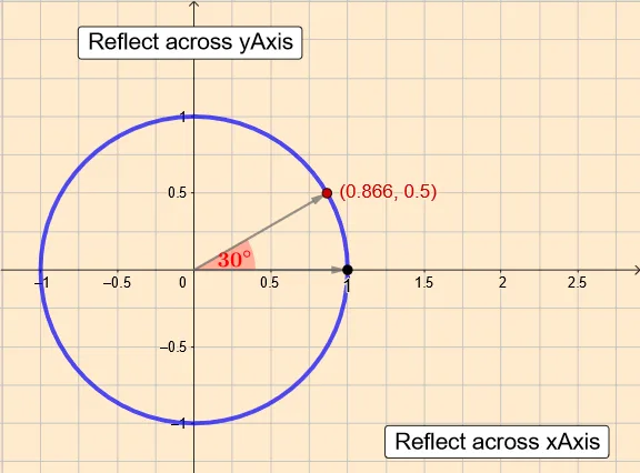
This GeoGebra example demonstrates the symmetry of the unit circle, illustrating the behavior of trigonometric functions such as sine and cosine on the circle. Key mathematical concepts include the unit circle, trigonometric functions, symmetry, sequences, and introductory calculus. The construction employs GeoGebra commands like Sequence to generate point sequences, Point to define key points, AngularBisector to create angle bisectors, Intersect to find intersections, Dilate for scaling, Sector to draw sectors, and Vector to represent vectors. Objects such as lines, points, angles, and vectors work together to build an interactive model. This example is suitable for high school students reinforcing trigonometry knowledge or college freshmen exploring related calculus concepts.
GeoGebra Commands & Parameters
Sequence((cos(n°), sin(n°)), n, -180, 180, 5) → l1Point(l1) → PAngularBisector(A, O, P) → hIntersect(eq1, h, 2) → P_1Dilate(A, 0.4) → A'Dilate(P, 0.4) → P'Sector(Dilate[eq1, 0.4], A', P') → cVector(P) → fVector(A) → gDilate(P_1, 0.25) → P_2Sector(Dilate[eq1, 0.4], P', A') → dVector(Q) → uVector(R) → vDilate(A, 0.4) → A'_1Dilate(Q, 0.4) → Q'Sector(Dilate[eq1, 0.45], A'_1, Q') → eDilate(R, 0.45) → R'Dilate(A, 0.45) → A'_2Sector(Dilate[eq1, 0.45], R', A'_2) → kDilate(A, 0.45) → A'_3Dilate(R, 0.45) → R'_1Sector(Dilate[eq1, 0.45], A'_3, R'_1) → p
AI Drawing Prompt Reference
Create an interactive diagram exploring symmetry on the unit circle. On a coordinate plane, generate several points lying on the unit circle from approximately −180° to 180° using an angle-parameter point sequence, then select one reference point and form the corresponding radius direction from the origin. Construct the angle bisector determined by that reference point, the origin, and the relevant radius direction, and use this to locate a symmetry-related intersection point. Scale certain original points outward by a fixed factor to obtain corresponding outer points, then draw multiple sector (wedge) regions with shared reference rays and these scaled points as endpoints. Add arrows representing vectors from the origin and from key points to illustrate how the sine/cosine behavior reflects symmetry across the constructed bisector and rays.
The prompt above was compiled from the original drawing commands and is for reference only.