
Rotational Symmetry in Action: Kite with Incircle
Loading the math board and drawing, please wait…
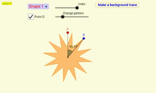
① This example dynamically demonstrates rotational symmetry using a kite shape combined with an incircle, allowing users to observe how the figure coincides with itself after rotation about its center. ② Core mathematical concepts include rotational symmetry, symmetry axes, incircles, right triangles, trigonometry (angle calculations), and the use of equations and sequences. ③ Construction highlights: Based on the construction summary, GeoGebra commands such as SelectedIndex, Line, Circle, Point, Intersect, Angle, If, Sequence, DynamicCoordinates, Join, Polygon, and Segment are used to build multiple points (e.g., A, B, C, P), segments, polygons (PolyPtA etc.), and dynamic coordinates, with angles α, β and sliders controlling rotation for an interactive symmetry display. ④ Suitable for middle or high school geometry classes or enrichment activities, this example helps students explore properties of rotational symmetry, relationships between incircles and polygons, and dynamic geometric construction using GeoGebra.
GeoGebra Commands & Parameters
SelectedIndex(Bahasa) → nnLine(O, yAxis) → fCircle(O, Rd) → cPoint(c) → CIntersect(c, f, 2) → AAngle(C, O, A) → αIf(round(α / ° / (360 / a)) ≟ 0, a, round(α / ° / (360 / a))) → NearSequence(Rotate[A, (((-n) * 360 / a))°, O], n, 1, a) → Pt0If(Distance[C, Pt0(Near)] < 0.15, Pt0(Near), C) → PDynamicCoordinates(C, x(P), y(P)) → BCircle(Rotate[B, (360 / a)°, O], Jarak) → eCircle(B, Jarak) → dIntersect(d, e) → F, G, ,If(Distance[O, F] < Distance[O, G], F, G) → HIf(nn ≟ 1, {"Shape 1", "Shape 2", "Shape 3", "Shape 4", "Shape 5", "Shape 6"}, {"Bentuk 1", "Bentuk 2", "Bentuk 3", "Bentuk 4", "Bentuk 5", "Bentuk 6"}) → BentukSelectedIndex(Bentuk) → mSequence(Rotate[H, ((n * 360 / a))°, O], n, 1, a) → Pt2Sequence(Rotate[B, ((n * 360 / a))°, O], n, 1, a) → Pt1Join(Sequence[{Pt1(n), Pt2(n)}, n, 1, a]) → PolyPtAPolygon(PolyPtA) → Bentuk1Segment(O, A) → hAngle(B, O, A) → βSegment(O, B) → jJoin(Sequence[{Pt1(n), Pt1(n + 1), Pt2(n), Pt2(a - n + 1)}, n, 1, a, 2]) → PolyPtCPolygon(PolyPtC) → Bentuk3Join(Sequence[{Pt1(n), Pt1(n + 1), Pt2(n + 1)}, n, 1, a, 2]) → PolyPtBPolygon(PolyPtB) → Bentuk2Join(Sequence[{Pt1(n), Pt2(a - n + 1)}, n, 1, a]) → PolyPtEPolygon(PolyPtE) → Bentuk5Join(Sequence[{Pt1(n), Pt1(n + 1), Pt2(n)}, n, 1, a, 2]) → PolyPtDPolygon(PolyPtD) → Bentuk4If(Distance[O, F] < Distance[O, G], G, F) → JSequence(Rotate[J, ((n * 360 / a))°, O], n, 1, a) → Pt3Join(Sequence[{Pt1(n), Pt2(n), Pt3(n), Pt2(n + 1)}, n, 1, a, 2]) → PolyPtFPolygon(PolyPtF) → Bentuk6
AI Drawing Prompt Reference
Draw a dynamic geometric figure demonstrating rotational symmetry: start with a circle centered at a point, place a point on the circle, and connect the center to two circle points to form an angle. Rotate this point around the center by equal steps to generate multiple symmetric points, then connect these points to form several overlapping polygons (like kites and triangles). The figure shows multiple layers of rotated shapes that coincide after rotation, with angle labels, illustrating rotational symmetry.
The prompt above was compiled from the original drawing commands and is for reference only.