
Rotational Symmetry by Mr. Krebs
Loading the math board and drawing, please wait…
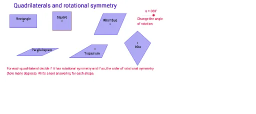
This example demonstrates the phenomenon of a shape coinciding with its original position after rotation by a certain angle. It involves core mathematical concepts such as symmetry, rotation angles, and polygon construction. Key GeoGebra commands used include Segment, OrthogonalLine, Point, Intersect, Polygon, Circle, Line, Rotate, Mirror for constructing and transforming the图形. It is suitable for high school students learning geometric transformations and symmetry.
GeoGebra Commands & Parameters
Segment(A, B) → aOrthogonalLine(A, a) → bOrthogonalLine(B, a) → cPoint(b) → COrthogonalLine(C, b) → dIntersect(c, d) → DPolygon(C, D, B, A) → poly1, c_1, d_1, b_1, a_1Segment(C, B) → eSegment(D, A) → fIntersect(e, f) → EPolygon(F, G, 4) → poly2, f_1, g, h, i, H, ISegment(I, G) → jSegment(H, F) → kIntersect(j, k) → JSegment(K, L) → lCircle(K, L) → pPoint(p) → MSegment(K, M) → mLine(M, l) → nLine(L, m) → qIntersect(n, q) → NSegment(M, L) → rSegment(N, K) → sIntersect(r, s) → OPolygon(M, N, L, K) → poly3, m_1, n_1, l_1, k_1Rotate(C, (-α), E) → C'Rotate(D, (-α), E) → D'Rotate(B, (-α), E) → B'Rotate(A, (-α), E) → A'Polygon(C', D', B', A') → poly1', c', d', b', a'Rotate(M, (-α), O) → M'Rotate(N, (-α), O) → N'Rotate(L, (-α), O) → L'Rotate(K, (-α), O) → K'Polygon(M', N', L', K') → poly3', m', n', l', k'Segment(P, Q) → tSegment(P, R) → e_1Line(Q, e_1) → g_1Line(R, t) → h_1Intersect(g_1, h_1) → SPolygon(P, R, S, Q) → poly4, p_1, r_1, s_1, q_1Segment(R, Q) → i_1Segment(S, P) → j_1Intersect(i_1, j_1) → TRotate(P, (-α), T) → P'Rotate(R, (-α), T) → R'Rotate(S, (-α), T) → S'Rotate(Q, (-α), T) → Q'Polygon(P', R', S', Q') → poly4', p', r', s', q'Segment(U, V) → t_1Segment(U, W) → a_2Line(W, t_1) → b_2Point(b_2) → ZSegment(Z, V) → c_2Polygon(U, V, Z, W) → poly5, u, v, z, wSegment(W, V) → d_2Segment(Z, U) → e_2Intersect(d_2, e_2) → A_1Rotate(U, (-α), A_1) → U'Rotate(V, (-α), A_1) → V'Rotate(Z, (-α), A_1) → Z'Rotate(W, (-α), A_1) → W'Polygon(U', V', Z', W') → poly5', u', v', z', w'Line(B_1, C_1) → f_2Mirror(D_1, f_2) → E_1Polygon(D_1, B_1, E_1, C_1) → poly6, d_3, b_3, e_3, c_3Segment(D_1, E_1) → g_2Intersect(f_2, g_2) → F_1Rotate(D_1, (-α), F_1) → G_1Rotate(B_1, (-α), F_1) → H_1Rotate(E_1, (-α), F_1) → I_1Rotate(C_1, (-α), F_1) → J_1Polygon(G_1, H_1, I_1, J_1) → poly6', g_3, h_2, i_2, j_2Rotate(poly2, (-α), J) → poly2'
AI Drawing Prompt Reference
Draw a geometric figure demonstrating rotational symmetry. Construct a rectangle, a square, and a parallelogram, each with its diagonals intersecting at a center point. Rotate each polygon around its own center by the same angle so that the rotated image coincides with the original, showing symmetry. Use line segments to connect key vertices and keep construction lines visible to illustrate the process.
The prompt above was compiled from the original drawing commands and is for reference only.