
Rectangle—All: Geometric Construction with Angles
Loading the math board and drawing, please wait…
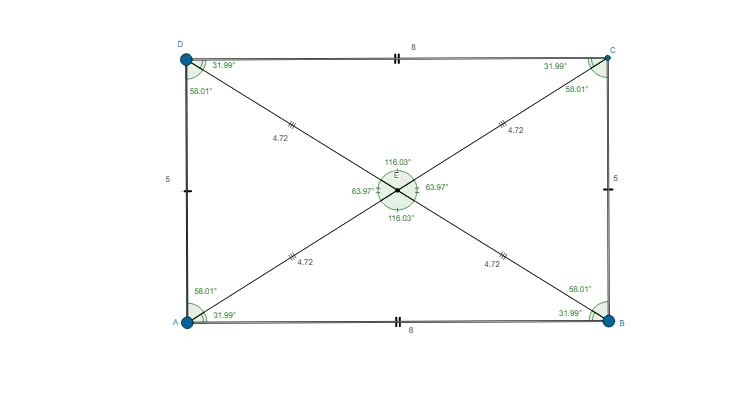
This example demonstrates how to construct rectangles in the plane using geometric constraints, with angles and right-angle relationships built into the construction. It focuses on key geometry ideas: adjacent sides of a rectangle are perpendicular, and the rectangle is determined by controlled directions, intersection points, and angle verification. The construction uses GeoGebra tools to: define sides with Segment; create perpendicular edges via OrthogonalLine; generate and place vertices using Point and Intersect; measure and confirm essential properties with Angle (e.g., checking for right-angle conditions); and finally build the rectangle using Polygon (such as poly1), along with labeled angle variables (α, β, γ, δ, etc.). Suitable for middle and high school geometry lessons, especially for demonstrating geometric construction workflows and verifying rectangle properties visually.
GeoGebra Commands & Parameters
Segment(A, B) → aOrthogonalLine(A, a) → bOrthogonalLine(B, a) → cPoint(b) → DOrthogonalLine(D, b) → dIntersect(c, d) → CSegment(D, A) → eSegment(D, C) → fSegment(C, B) → gAngle(C, B, A) → αAngle(B, A, D) → βAngle(A, D, C) → γAngle(D, C, B) → δPolygon(A, B, C, D) → poly1, a_1, b_1, c_1, d_1Segment(A, C) → hSegment(D, B) → iIntersect(h, i) → ESegment(D, E) → jSegment(A, E) → kSegment(E, C) → lSegment(E, B) → mAngle(E, D, C) → εAngle(E, A, D) → ζAngle(E, B, A) → ηAngle(E, C, B) → θAngle(D, C, E) → ιAngle(C, B, E) → κAngle(B, A, E) → λAngle(A, D, E) → μAngle(D, E, A) → νAngle(A, E, B) → ξAngle(B, E, C) → οAngle(C, E, D) → ρ
AI Drawing Prompt Reference
Construct a rectangle in the plane using geometric constraints and angle verification. Start with a base edge segment, then draw lines through its endpoints that are perpendicular to the base direction. Use the intersections of these perpendicular lines to locate the remaining two vertices, then connect the four vertices to form a closed quadrilateral. Draw the relevant diagonal and additional connecting segments from the diagonal intersection to the vertices, and measure the angles at each corner (and at the auxiliary intersection) to confirm right-angle relationships. Label the angle measures during the construction so the rectangle’s angle consistency is visible.
The prompt above was compiled from the original drawing commands and is for reference only.