
Pouring Water into a Cylinder: Modeling Volume–Height Change
Loading the math board and drawing, please wait…
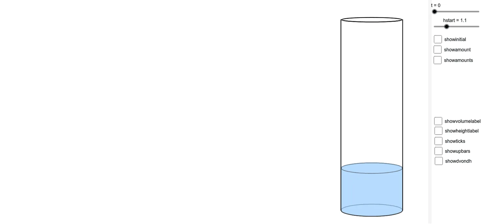
This example visually simulates pouring water into a cylinder and lets learners observe the relationship between the water volume and the water height as the process evolves. It emphasizes how geometric parameters translate into functional dependence and how changes can be analyzed through calculus. Key mathematical ideas include cylindrical geometry (volume–height proportional structure), parameter-driven modeling of evolving quantities (height h versus volume vol), and calculus tools to study variation and possible extremes. Construction in GeoGebra combines numerical and geometric components: Derivative is used to represent instantaneous rates of change; Max helps identify or compare extremal values of relevant quantities; Circle, Line, Intersect, Segment, Ellipse, Polygon, Arc, and Rotate build the cylinder’s cross-sectional geometry and auxiliary shapes; OrthogonalLine, Angle, and Distance compute measurements such as lengths and angles; Sequence generates parameter-dependent values; IntegralBetween models accumulated volume/height over a given interval; Vector and Text provide direction cues and labels for interpreting the evolving model. Suitable for advanced secondary education and early university calculus/modeling courses, especially for demonstrating how a physical process can be represented and analyzed with geometry and calculus in an interactive graphing environment.
GeoGebra Commands & Parameters
Derivative(w) → rMax(r, 0, tmax) → maxrptCircle(pcenter, 5) → pcircleLine(pcenter, (x(pcenter) + 1, y(pcenter))) → phlineIntersect(pcircle, phline, 2) → phlineptRotate(phlinept, pth, pcenter) → phlinept2Line(pcenter, phlinept2) → phline3Intersect(pcircle, phline3, 1) → ppt1OrthogonalLine(ppt1, phline3) → phline4Point(phline4) → ptippt1Circle(pcenter, ptipcircleradius) → ptipcircleSegment(pcenter, ptippt1) → ptiplineIntersect(ptipcircle, ptipline) → ptippt,Distance(ptippt, pcenter) → ptipradiusAngle(phlinept, pcenter, phlinept2) → pouranglePoint({cradius, 0}) → cpt1Point({(-cradius), 0}) → cpt2Point({(-cradius), cheight}) → cpt3Segment(cpt2, cpt3) → cleftsegPoint({0, wheight}) → wheightptPoint({cradius, wheight}) → wheightpt1Point({(-cradius), wheight}) → wheightpt2Point({0, cheight - cscalemin}) → cptellipsemidtopEllipse((x(cpt) - 0.02, cheight), (x(cpt3) + 0.02, cheight), cptellipsemidtop) → cellipsetopSegment(cpt1, cpt) → crightsegPoint({0, wheight - (cscalemax - (wheight / cheight * cscalerange))}) → wptellipsemidEllipse((x(wheightpt1) - 0.02, wheight), (x(wheightpt2) + 0.02, wheight), wptellipsemid) → wellipsetopPoint({0, (-cscalemax)}) → cptellipsemidbottomEllipse((x(cpt1) - 0.02, 0), (x(cpt2) + 0.02, 0), cptellipsemidbottom) → cellipsebottomPolygon(wheightpt1, cpt1, cpt2, wheightpt2) → cwater, wheightpt1_1, cpt1_1, cpt2_1, wheightpt2_1Arc(cellipsebottom, cpt2, cpt1) → warcbottomArc(wellipsetop, wheightpt1, wheightpt2) → warctopPoint({((sscale * rscale) * r(t)), wheight}) → spt1Point({(((-sscale) * rscale) * r(t)), wheight}) → spt2Circle(pcenter, ptipradius - (((spscale * rscale) * ptipradius) * r(t))) → scircleIntersect(scircle, ptipline) → spt3,Polygon(ptippt, spt3, spt1, spt2) → swater, ptippt_1, spt3_1, spt1_1, spt2_1Point({0, wheight - (0.2 * (cscalemax - (wheight / cheight * cscalerange)))}) → sellipseptEllipse(spt1, spt2, sellipsept) → sellipseArc(sellipse, spt2, spt1) → sarcArc(sellipse, spt2, spt1) → ssplashArc(cellipsetop, cpt3, cpt) → cellipsetoparcSequence(hstart + (k * dh), k, 0, n) → wheightsSequence(Point[{0, Element[wheights, k] - (cscalemax - (Element[wheights, k] / cheight * cscalerange))}], k, 2, n + 1) → wellipsemidptsSequence(Ellipse[((-cradius) + 0.02, Element[wheights, k]), (cradius - 0.02, Element[wheights, k]), Element[wellipsemidpts, k - 1]], k, 2, n + 1) → wellipsesArc(cellipsebottom, cpt2, cpt1) → carcbottomSequence(Arc[Element[wellipses, k], ((-cradius), Element[wheights, k + 1]), (cradius, Element[wheights, k + 1])], k, 1, n) → warcfrontSequence(Arc[Element[wellipses, k], (cradius, Element[wheights, k + 1]), ((-cradius), Element[wheights, k + 1])], k, 1, n) → warcbackIntegralBetween(whitetopline, efuntop, (-cradius), cradius) → whitetopIntegralBetween(efunbottom, whitebottomline, (-cradius), cradius) → whitebottomPoint({0, hstart - (cscalemax - (hstart / cheight * cscalerange))}) → wptstartellipsemidEllipse(((-cradius) + 0.02, hstart), (cradius - 0.02, hstart), wptstartellipsemid) → wstartellipseArc(wstartellipse, ((-cradius) + 0.02, hstart), (cradius - 0.02, hstart)) → wstartfrontellipseArc(wstartellipse, (cradius - 0.02, hstart), ((-cradius) + 0.02, hstart)) → wstartbackellipseSequence(Segment[((-cradius) - 0.36, Element[wheights, k]), ((-cradius) - 0.08, Element[wheights, k])], k, 1, n + 1) → hlinesSequence(Vector[((-cradius) - 0.22, Element[wheights, k]), ((-cradius) - 0.22, Element[wheights, k + 1])], k, 1, n) → wvecsVector(((-cradius) - 0.22, (n * dh) + hstart), ((-cradius) - 0.22, wheight)) → wlastvecSegment(((-cradius) - 0.08, 0), ((-cradius) - 0.36, 0)) → wstartlineSegment(((-cradius) - 0.36, wheight), ((-cradius) - 0.08, wheight)) → hendlinePolygon(((-2 * cradius), ((j + 1) * dh) + hstart + 0.008), ((-2 * cradius), 10), ((-cradius) + 0.006, 10), ((-cradius) + 0.006, ((j + 1) * dh) + hstart + 0.008)) → cwhitetoprec, wr3, wr4, wr5, wr6Polygon(((-2 * cradius), (j * dh) + hstart - 0.008), ((-2 * cradius), -10), ((-cradius) + 0.006, -10), ((-cradius) + 0.006, (j * dh) + hstart - 0.008)) → cwhitebottomrec, f, g, h, iPolygon(((2 * cradius), (j * dh) + hstart - 0.008), ((2 * cradius), -10), (cradius - 0.006, -10), (cradius - 0.006, (j * dh) + hstart - 0.008)) → cwhitebottomrecright, wr11, wr12, wr1, wr2Polygon(((2 * cradius), ((j + 1) * dh) + hstart + 0.008), ((2 * cradius), 10), (cradius - 0.006, 10), (cradius - 0.006, ((j + 1) * dh) + hstart + 0.008)) → cwhiteroprecright, k, l, q, cVector(((-cradius) - 0.22, 0), ((-cradius) - 0.22, hstart)) → wstartvecVector(((-cradius) - 0.22, hstart), ((-cradius) - 0.22, wheight)) → wvecSegment(((-cradius) - 0.08, hstart), ((-cradius) - 0.36, hstart)) → hstartlinePolygon((qxloc + ((p * dh) * j) - qos, -10), (qxloc - 2, -10), (qxloc - 2, 10), (qxloc + hstart + (j * dh) - qos, 10), (qxloc + hstart + (j * dh) - qos, qhloc - 0.16), (qxloc + ((p * dh) * j) - qos, qvloc + 0.16)) → qwhitebefore, d, e, f_1, g_1, h_1, i_1Polygon((qxloc + ((p * dh) * (j + 1)) + qos, -10), ((-2 * cradius), -10), ((-2 * cradius), 10), (qxloc + hstart + ((j + 1) * dh) + qos, 10), (qxloc + hstart + ((j + 1) * dh) + qos, qhloc - 0.16), (qxloc + ((p * dh) * (j + 1)) + qos, qvloc + 0.16)) → qwhiteafter, s, j_1, k_1, l_1, m_1, n_1Sequence(Point[{-0.18, y(Element[wellipsemidpts, k]) + (y(Element[wellipsemidpts, k + 1]) - y(Element[wellipsemidpts, k])) / 2 + 0.12}], k, 1, n) → cdvlabelptsSequence(Text["\Delta v", Element[cdvlabelpts, k], true, true], k, 1, n) → cdvlabelsPoint({-0.18, y(wptstartellipsemid) + (y(Element[wellipsemidpts, 1]) - y(wptstartellipsemid)) / 2 + 0.12}) → cdvlabelstartptPoint({-0.18, y(Element[wellipsemidpts, n]) + (y(wptellipsemid) - y(Element[wellipsemidpts, n])) / 2 + 0.12}) → cdvlabelendptText("\Delta v", cdvlabelstartpt, true, true) → cdvlabelstartText("\Delta v", cdvlabelendpt, true, true) → cdvlabelendSequence(Point[{(-cradius) - 0.7, Element[wheights, k] + dh / 2 + 0.12}], k, 1, n) → cdhlabelptsSequence(Text["\Delta h", Element[cdhlabelpts, k], true, true], k, 1, n) → cdhlabelsPoint({(-cradius) - 0.7, Element[wheights, n + 1] + (wheight - Element[wheights, n + 1]) / 2 + 0.12}) → cdhlabelendptText("\Delta h", cdhlabelendpt, true, true) → cdhlabelendSequence(Point[{qxloc + Element[wheights, k] + (1 / 2 * dh) - 0.12, qhloc + 0.34}], k, 1, n) → qdhlabelptsPoint({qxloc + Element[wheights, n + 1] + (wheight - Element[wheights, n + 1]) / 2 - 0.12, qhloc + 0.34}) → qdhlabelendptSequence(Text["\Delta h", Element[qdhlabelpts, k], true, true], k, 1, n) → qdhlabelsText("\Delta h", qdhlabelendpt, true, true) → qdhlabelendSequence(Point[{qxloc + ((p * dh) * (k - 1 / 2)) - 0.135, qvloc - 0.16}], k, 1, n) → qdvlabelptsPoint({qxloc + ((p * dh) * n) + (vol - ((p * dh) * n)) / 2 - 0.135, qvloc - 0.16}) → qdvlabelendptText("\Delta v", qdvlabelendpt, true, true) → qdvlabelendSequence(Text["\Delta v", Element[qdvlabelpts, k], true, true], k, 1, n) → qdvlabelsPoint({-0.26, hstart + (wheight - hstart) / 2 + 0.07}) → cvlabelptText("\Delta v", cvlabelpt, true, true) → cvlabelPoint({(-cradius) - 0.85, hstart + (wheight - hstart) / 2 + 0.2}) → chlabelptText("\Delta h", chlabelpt, true, true) → chlabelPoint({qxloc + vol / 2 - 0.18, qvloc - 0.14}) → qvlabelptText("\Delta v", qvlabelpt, true, true) → qvlabelPoint({qxloc + hstart + (wheight - hstart) / 2 - 0.17, qhloc + 0.38}) → qhlabelptText("\Delta h", qhlabelpt, true, true) → qhlabelSegment((qxloc + vol, qvloc + 0.16), (qxloc + vol, qvloc - 0.16)) → qvendlineVector((qxloc, qvloc), (qxloc + vol, qvloc)) → qvvecSegment((qxloc, qvloc + 0.16), (qxloc, qvloc - 0.16)) → qvstartlineSegment((qxloc + wheight, qhloc - 0.16), (qxloc + wheight, qhloc + 0.16)) → qhendlineVector((qxloc + hstart, qhloc), (qxloc + wheight, qhloc)) → qhvecSegment((qxloc + hstart, qhloc - 0.16), (qxloc + hstart, qhloc + 0.16)) → qhstartlineSegment((qxloc, qhloc - 0.16), (qxloc, qhloc + 0.16)) → qwstartlineSegment((qxloc + vol, qvloc + 0.16), (qxloc + wheight, qhloc - 0.16)) → quplinelastSegment((qxloc, qvloc + 0.16), (qxloc + hstart, qhloc - 0.16)) → quplinefirstSegment((qxloc + hstart + vol, qhloc + 0.16), (qxloc + hstart + vol, qhloc - 0.16)) → qonhendlineSequence(Segment[(qxloc + hstart + (k * vol), qhloc + 0.16), (qxloc + hstart + (k * vol), qhloc - 0.16)], k, 0, m) → qonhlinesSegment((qxloc + vol, qvloc + 0.16), (qxloc + hstart + vol, qhloc - 0.16)) → qonhenduplineSequence(Segment[(qxloc + Element[wheights, k], qhloc - 0.16), (qxloc + Element[wheights, k], qhloc + 0.16)], k, 1, n + 1) → qhlinesSequence(Vector[(qxloc + ((p * dh) * k), qvloc), (qxloc + ((p * dh) * (k + 1)), qvloc)], k, 0, n - 1) → qvvecsVector((qxloc + ((p * dh) * n), qvloc), (qxloc + vol, qvloc)) → qvlastvecSequence(Segment[(qxloc + ((p * dh) * k), qvloc + 0.16), (qxloc + ((p * dh) * k), qvloc - 0.16)], k, 0, n) → qvlinesSequence(Segment[(qxloc + ((p * dh) * k), qvloc + 0.16), (qxloc + Element[wheights, k + 1], qhloc - 0.16)], k, 0, n) → quplinesVector((qxloc + vol, qvloc), (qxloc + vol, qvloc + wheight - hstart)) → quphvecSequence(Point[{qxloc + ((p * dh) * k), qvloc + dh}], k, 1, n) → qupvecptsSequence(Point[{qxloc + Element[wheights, k], qhloc}], k, 2, n + 1) → qhvecendptsSequence(Point[{x(Element[qhvecendpts, k]) + (rot * (x(Element[qupvecpts, k]) - x(Element[qhvecendpts, k]))), y(Element[qhvecendpts, k]) + (rot * (y(Element[qupvecpts, k]) - y(Element[qhvecendpts, k])))}], k, 1, n) → qhvecptsSequence(Vector[((dh * cos(π + rota)) + x(Element[qhvecpts, k]), (dh * sin(π + rota)) + y(Element[qhvecpts, k])), Element[qhvecpts, k]], k, 1, n) → qhrotvecsPoint({qxloc + wheight, qhloc}) → qhlastptPoint({qxloc + vol, qvloc + wheight - (n * dh) - hstart}) → quplastptPoint({x(qhlastpt) + (rot * (x(quplastpt) - x(qhlastpt))), y(qhlastpt) + (rot * (y(quplastpt) - y(qhlastpt)))}) → qhlastvecptVector(((qhlastveclength * cos(π + rota)) + x(qhlastvecpt), (qhlastveclength * sin(π + rota)) + y(qhlastvecpt)), qhlastvecpt) → qhlastrotvecVector((((dh + hstart) * cos(π + rota)) + qxloc + hstart + dh - (rot * (hstart + dh)), ((dh + hstart) * sin(π + rota)) + qhloc - (rot * (qhloc - (qvloc + dh)))), ((dh * cos(π + rota)) + qxloc + hstart + dh - (rot * (hstart + dh)), (dh * sin(π + rota)) + qhloc - (rot * (qhloc - (qvloc + dh))))) → qhstartvec
AI Drawing Prompt Reference
Create a dynamic side-view construction that models pouring water into a cylinder. Start by drawing the cylinder cross-section circle with a fixed center and radius, then add a reference line through the center and form a rotated line to set the pouring direction, using their intersections on the circle to define key points. Build the initial water boundary with circle arcs and a polygonal water region inside the cylinder. Generate a stack of intermediate liquid levels: at multiple heights, place points on the vertical axis and construct corresponding ellipses whose endpoints lie near the left and right interior sides, then connect these ellipses using arc segments to form top “wave” arcs. Include short segments and arc annotations that link the liquid-level points to the cylinder boundary so the evolving water shape reflects the height–volume geometric dependence.
The prompt above was compiled from the original drawing commands and is for reference only.