
Pendulum Tension Derivation
Loading the math board and drawing, please wait…
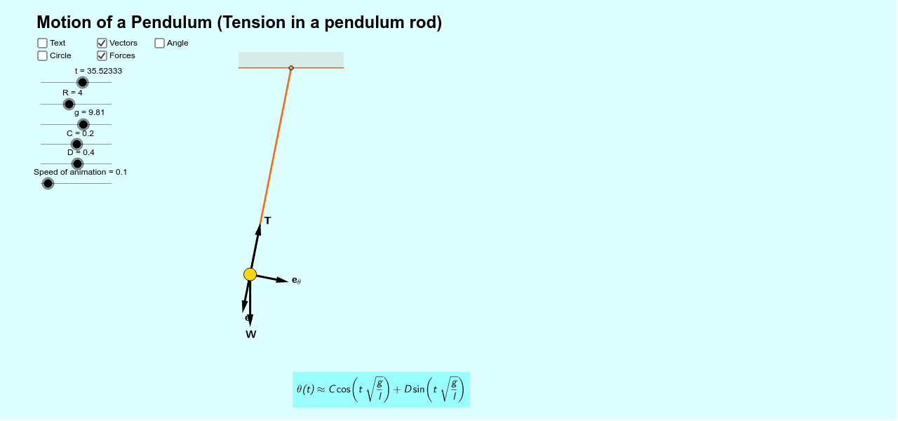
This example demonstrates the derivation of tension in a pendulum rod using Newtonian mechanics. Key math concepts include trigonometry, coordinate geometry, and calculus. Constructed with commands like Rotate, Angle, Segment, Vector, Polygon, and objects such as D, C, g, R, Hinge, P, t, Bob, θ, Speed. Ideal for high school physics and mathematics education to understand pendulum motion and force analysis.
GeoGebra Commands & Parameters
Rotate(P, (C * cos((t * sqrt(g / R)))) + (D * sin((t * sqrt(g / R)))), Hinge) → BobAngle(P, Hinge, Bob) → θSegment(Bob, Hinge) → RodVector(Bob, (x(Bob), y(Bob) - 1)) → WVector(Bob, (x(Bob) - sin(θ), y(Bob) + cos(θ))) → TVector(Bob, (x(Bob) + (z * sin(θ)), y(Bob) - (z * cos(θ)))) → e_rVector(Bob, (x(Bob) + (z * cos(θ)), y(Bob) + (z * sin(θ)))) → e_θPolygon(O, O', O'', O''') → Ceiling, o, o', o'', o'''
AI Drawing Prompt Reference
Draw a diagram showing the tension in a pendulum rod, including a fixed point, a pivot point, and a pendulum bob swinging around the pivot. Display the velocity vector and tension vector of the bob, along with the directions of the unit radial and tangential vectors, set against a simple ceiling background to represent the悬挂 environment.
The prompt above was compiled from the original drawing commands and is for reference only.