
Orthogonality in Geometric Constructions: Perpendicular Lines and Angle Constrai
Loading the math board and drawing, please wait…
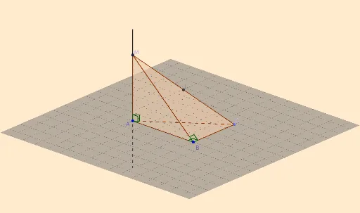
This GeoGebra example demonstrates orthogonality by constructing perpendicular lines within a larger geometric configuration. It visualizes how a right-angle (perpendicular) constraint translates into measurable angle relationships among lines and polygonal regions. Key concepts include orthogonality (perpendicular lines), angle construction and measurement (Angle), midpoint-based construction (Midpoint), and structured geometry built from points, lines, and polygons (interpretable in a 3D/space-aware setting). Construction workflow: Line creates the main line framework; OrthogonalLine generates lines perpendicular to a chosen line; Point defines the key vertices (e.g., A, B and others); Polygon builds several polygonal parts to organize the configuration; Angle displays the relevant angles (α, β, γ, δ) to verify the perpendicular and angular relationships; Midpoint introduces midpoints (e.g., M, m) to support symmetric or constrained geometry. Suitable for advanced secondary students and early university learners for teaching perpendicular conditions, angle-based reasoning, and geometric construction techniques.
GeoGebra Commands & Parameters
Line(A, B) → aOrthogonalLine(B, a, xOyPlane) → bPoint(b) → CPolygon(A, B, C) → poly1, c, a_1, b_1Angle(C, B, A, xOyPlane) → αOrthogonalLine(A, xOyPlane) → dPoint(d) → MPolygon(M, A, B) → poly2, b_2, m, a_2Polygon(M, A, C) → poly3, c_1, m_1, a_3Polygon(M, B, C) → poly4, c_2, m_2, b_3Angle(B, A, M) → βAngle(M, A, C) → γAngle(C, B, M) → δMidpoint(a_3) → I
AI Drawing Prompt Reference
Draw a geometry construction in a plane: start with two given points A and B and connect them to form a main line. Through point B, construct a line perpendicular to the main line and mark a key point C on that perpendicular. Build a polygonal region (a triangle) using A, B, and C. Next, construct another perpendicular line through A and choose its key point M on it. Form additional polygonal regions by connecting M with A and B, with M and A and C, and with M and B and C. Add angle measurements at the relevant vertices to display the relationships between these lines and the right-angle condition (angles labeled like α, β, γ, δ). Finally, introduce a midpoint I on the corresponding constructed segment to support the symmetric placement.
The prompt above was compiled from the original drawing commands and is for reference only.