
Oblique Projection Prism
Loading the math board and drawing, please wait…
In collections
Surface Area
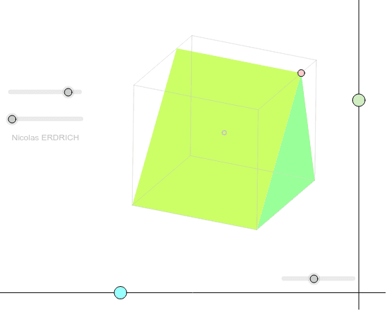
This example demonstrates the construction of an oblique projection prism. Key mathematical concepts include the geometry of a prism and its projection. Using GeoGebra commands such as Point, Segment, and Polygon, the faces of the prism are constructed, and the prism is translated using the Translate command. Suitable for high school students learning solid geometry.
GeoGebra Commands & Parameters
Point(xAxis) → OOrthogonalLine(O, xAxis) → kPoint(k) → TPoint(k) → SOrthogonalLine(S, k) → g_1Point(g_1) → PSequence(Mat * Element[cube, k], k, 1, 9) → cube'Sequence(I + (Element[cube', k, 1, 1], Element[cube', k, 2, 1]), k, 1, 9) → listepointsElement(listepoints, 1) → MElement(listepoints, 7) → LElement(listepoints, 8) → KElement(listepoints, 4) → JSegment(M, J) → m'Element(listepoints, 5) → NElement(listepoints, 2) → ASegment(A, M) → a'_1Element(listepoints, 6) → QPolygon(K, L, Q, N) → poly6, k_3, l_2, q_1, n_2Point(n_2) → RElement(listepoints, 3) → CPolygon(Q, A, C, L) → poly2, q, a_2, c_1, lPolygon(J, K, L, C) → poly4, j_2, k_1, l_1, c_5Line(R, k_1) → eIntersect(e, l_2) → FLine(F, q) → fIntersect(f, a_2) → GLine(G, a'_1) → gIntersect(g, m') → HElement(Element[AE, 3], 1) → droiteElement(AB, 3, 1) → avantElement(AC, 3, 1) → dessusPolygon(J, M, N, K) → poly5, j_3, m_1, n_1, k_2Polygon(J, C, A, M) → poly1, j, c, a_1, mPolygon(A, Q, N, M) → poly3, a_3, q_2, n, m_2Segment(J, C) → j'_1Segment(K, L) → k'_3Segment(L, Q) → l'_2Segment(N, K) → n'_2Segment(Q, N) → q'_1Segment(M, N) → m'_1Segment(Q, A) → q'Segment(K, J) → j'Segment(N, K) → l'Segment(C, L) → l''Segment(C, A) → l''''Segment(M, N) → k''''If(i ≟ 1, true, false) → hSegment(C, A) → k'''PointIn(poly2) → EPolygon(A, M, J, C) → poly10, p, s, t, b_1Polygon(C, F', A) → poly7, a_4, c_2, f'Polygon(J, R', M) → poly8, m_3, j_1, r'Segment(R, M) → d_1Line(J, M) → f_1Line(C, A) → h_1Segment(R, H) → e_1Translate(R_2, A - M) → Q_2Polygon(A, Q_2, R_2, M) → poly9, a_5, q_3, r_2, m_4Translate(R_3, C - J) → F_3Polygon(J, R_3, F_3, C) → poly11, j_4, r_3, f_3, c_3Angle(Line[M, J], Line[M, R']) → angAngle(Line[C, A], Line[C, F']) → ang2Angle(Line[A, M], Line[A, F']) → ang3Angle(Line[J, C], Line[J, R']) → ang4Angle(Line[C, J], Line[C, A]) → ang5
AI Drawing Prompt Reference
Draw an oblique projection prism by first taking point O on the x-axis and constructing a perpendicular line through O to get points T and S. Then, construct a perpendicular line through S to get point P. Next, use the Translate command to move the top face to form the prism's side faces. Finally, connect all points to form the prism's faces, including the top, bottom, and side faces, ensuring all segments and polygons are correctly connected.
The prompt above was compiled from the original drawing commands and is for reference only.