
Mother Line Construction
Loading the math board and drawing, please wait…
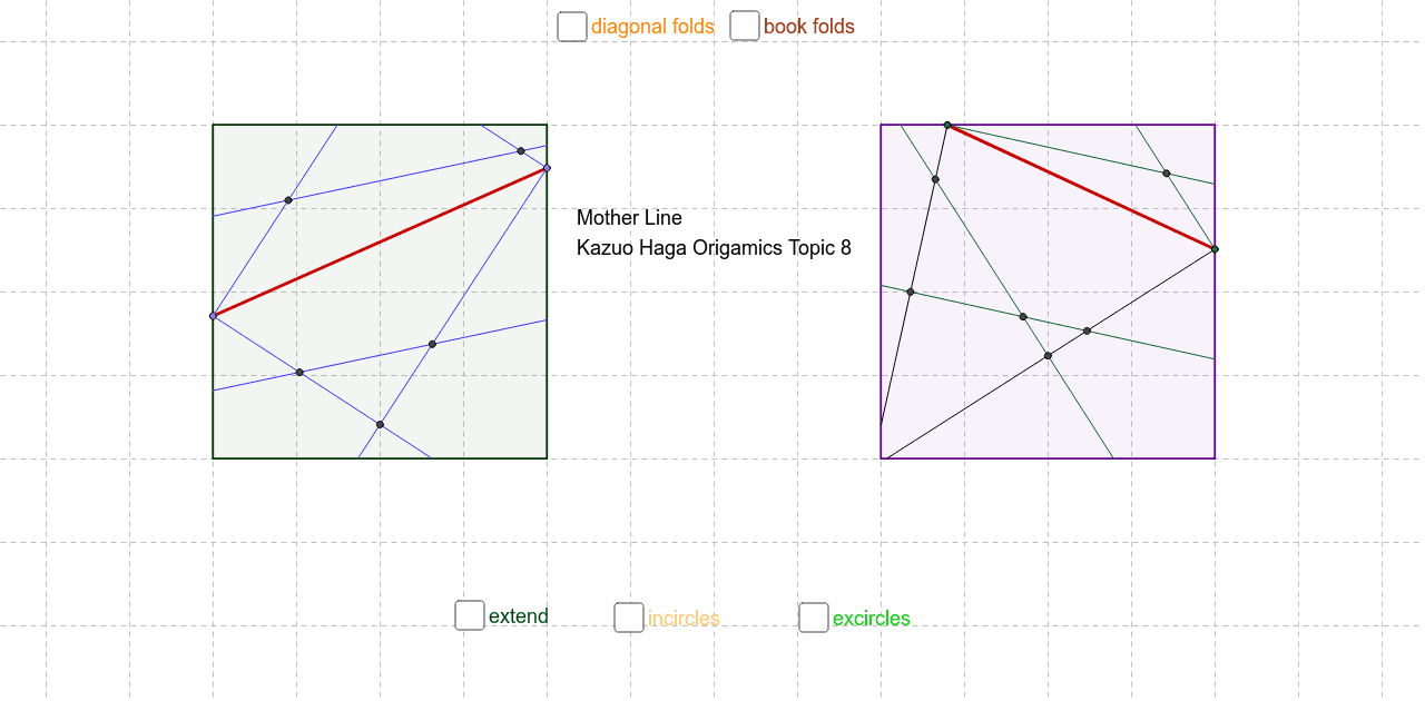
This applet demonstrates the mother line phenomenon discovered through folding activities. Key mathematical concepts include similar triangles and angle bisectors. Using GeoGebra commands such as Polygon, Point, Segment, and AngularBisector, complex geometric shapes can be constructed. Suitable for geometry construction demonstrations.
GeoGebra Commands & Parameters
Polygon(A, B, 4) → veelhoek1, a, b, c, d, C, DPolygon(I, J, 4) → veelhoek3, i, j, k, l, K, LPoint(d) → QPoint(b) → RSegment(Q, R) → rPoint(k) → UPoint(j) → VSegment(U, V) → tAngularBisector(d, r) → b_1, c_1AngularBisector(r, b) → d_1, e_1AngularBisector(r, a) → f_1, g_1AngularBisector(c, r) → h_1, i_1Intersect(e_1, c) → A_1Segment(A_1, R) → j_1Intersect(i_1, d) → B_1Intersect(i_1, b) → C_1Segment(B_1, C_1) → k_1Intersect(c_1, c) → D_1Segment(Q, D_1) → l_1Intersect(b_1, a) → E_1Segment(Q, E_1) → m_1Intersect(d_1, a) → F_1Segment(F_1, R) → n_1Intersect(f_1, d) → G_1Intersect(f_1, b) → H_1Segment(G_1, H_1) → p_1Intersect(j_1, l_1) → I_1Intersect(j_1, k_1) → J_1Intersect(k_1, l_1) → K_1Intersect(m_1, p_1) → L_1Intersect(n_1, p_1) → M_1Intersect(m_1, n_1) → N_1AngularBisector(t, k) → e, fAngularBisector(t, j) → g, hAngularBisector(t, l) → s, q_1AngularBisector(t, i) → r_1, s_1Intersect(s, k) → GIntersect(s, i) → HSegment(G, H) → t_1Intersect(g, i) → SSegment(S, V) → a_2Intersect(e, l) → TSegment(T, U) → b_2Intersect(f, j) → O_1Segment(U, O_1) → c_2Intersect(h, k) → P_1Segment(P_1, V) → d_2Intersect(r_1, l) → Q_1Intersect(r_1, j) → R_1Segment(Q_1, R_1) → e_2Intersect(g, l) → S_1Segment(S_1, V) → f_2Intersect(e, i) → T_1Segment(U, T_1) → g_2Intersect(t_1, g_2) → U_1Intersect(e_2, g_2) → V_1Intersect(f_2, g_2) → W_1Intersect(t_1, f_2) → Z_1Intersect(e_2, f_2) → A_2Intersect(c_2, d_2) → B_2Intersect(b_2, e_2) → C_2Intersect(t_1, b_2) → D_2Intersect(t_1, e_2) → E_2Intersect(t_1, a_2) → F_2Intersect(a_2, e_2) → G_2Point(c) → H_2Point(a) → I_2Segment(H_2, I_2) → h_2Point(d) → J_2Point(b) → K_2Segment(J_2, K_2) → i_2Intersect(b, c) → L_2Intersect(a, d) → M_2Segment(L_2, M_2) → j_2Point(k) → N_2Point(l) → P_2Point(j) → Q_2Segment(P_2, Q_2) → l_2Intersect(k, l) → R_2Intersect(i, j) → S_2Segment(R_2, S_2) → m_2Intersect(j, k) → T_2Intersect(i, l) → U_2Segment(T_2, U_2) → n_2Intersect(c, d) → V_2Intersect(a, b) → W_2Segment(V_2, W_2) → p_2Intersect(i, l) → Z_2Intersect(k, l) → A_3Ray(Z_2, A_3) → q_2Line(U, V) → r_2Intersect(i, j) → B_3Ray(Z_2, B_3) → s_2Intersect(r_2, q_2) → C_3Intersect(r_2, s_2) → OSegment(C_3, A_3) → mSegment(C_3, U) → nSegment(V, O) → pSegment(O, B_3) → qSegment(A_2, O) → a_1Segment(U_1, C_3) → t_2Intersect(j, e_2) → PSegment(P, O) → a_3Intersect(k, t_1) → WSegment(C_3, W) → b_3OrthogonalLine(E_2, t) → c_3Intersect(c_3, t) → ZCircle(E_2, Z) → d_3OrthogonalLine(B_2, t) → e_3Intersect(e_3, t) → D_3Circle(B_2, D_3) → f_3OrthogonalLine(U_1, t) → g_3Intersect(g_3, t) → E_3OrthogonalLine(U_1, l) → i_3Intersect(i_3, l) → F_3OrthogonalLine(D_2, k) → j_3Intersect(j_3, k) → G_3Ray(Q, R) → l_3Intersect(c, d) → H_3Intersect(b, c) → I_3Ray(H_3, I_3) → m_3Intersect(l_3, m_3) → J_3Segment(I_3, J_3) → n_3Segment(J_3, R) → p_3Intersect(b, k_1) → K_3Segment(K_3, J_3) → q_3OrthogonalLine(K_1, c) → r_3Intersect(r_3, c) → L_3Circle(K_1, L_3) → s_3Intersect(a, b) → M_3Intersect(a, d) → N_3Line(M_3, N_3) → t_3Line(R, Q) → a_4Intersect(t_3, a_4) → O_3Segment(O_3, Q) → b_4Segment(O_3, N_3) → c_4Intersect(d, p_1) → P_3Segment(O_3, P_3) → d_4OrthogonalLine(M_1, b) → e_4Intersect(e_4, b) → Q_3Circle(M_1, Q_3) → f_4OrthogonalLine(J_1, c) → g_4OrthogonalLine(L_1, a) → h_4Intersect(g_4, c) → R_3Intersect(h_4, a) → S_3Circle(J_1, R_3) → k_4Circle(L_1, S_3) → p_4OrthogonalLine(G_2, i) → i_4Intersect(i_4, i) → T_3Midpoint(k) → U_3Midpoint(i) → V_3Segment(U_3, V_3) → k_2OrthogonalLine(D_2, k) → h_3OrthogonalLine(G_2, i) → k_3Intersect(h_3, k) → W_3Intersect(k_3, i) → Z_3Circle(D_2, W_3) → q_4Circle(G_2, Z_3) → r_4OrthogonalLine(U_1, k) → j_4OrthogonalLine(A_2, i) → l_4Intersect(j_4, k) → A_4Intersect(l_4, i) → B_4Circle(U_1, A_4) → s_4Circle(A_2, B_4) → t_4
AI Drawing Prompt Reference
Draw a complex geometric figure composed of multiple triangles and segments. Start by drawing two quadrilaterals, then find the midpoints of their sides and diagonals to connect them with new segments. Use the angle bisector method to construct more segments and intersections from these segments, ultimately forming a complex figure made up of multiple triangles and segments.
The prompt above was compiled from the original drawing commands and is for reference only.