
Logic Gates Interactive Demo: Simulating AND, OR, NOT with Geometry
Loading the math board and drawing, please wait…
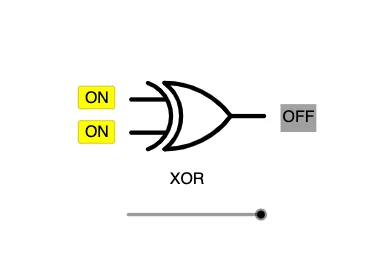
This GeoGebra example presents an interactive logic gate demonstration, using geometric elements such as segments, semicircles, and circular arcs to visually represent AND, OR, and NOT gates. The core mathematical concepts include Boolean logic, truth tables, and graphical representation of logical operations. Construction highlights: commands like Segment, Point, Semicircle, and CircumcircleArc are used to draw gate symbols; buttons (button1, button2, button3) toggle input states; conditional statements (if) and text objects (text2, text3) display outputs. Suitable for middle school or high school computer science and mathematics classes, this tool helps students intuitively grasp logic operations and basic circuit design.
GeoGebra Commands & Parameters
Segment(A, B) → fSegment(C, B) → gSegment(A, C) → hPoint(f) → DSegment(D, E) → iSegment(C, F) → jSegment(G, H) → kSegment(H, I) → lSegment(G, J) → mSemicircle(J, I) → cPoint(k) → LSegment(K, L) → pPoint(k) → NSegment(M, N) → qPoint(c) → OSegment(O, P) → rCircumcircleArc((-0.5, 3), (1.5, 2.5), O) → eCircumcircleArc((-0.5, 1), (1.5, 1.5), O) → sCircumcircleArc((-0.5, 3), (0.2, 2), (-0.5, 1)) → dCircumcircleArc((0, 3), (1.5, 2.5), O) → tCircumcircleArc((0, 1), (1.5, 1.5), O) → c_1CircumcircleArc((0, 3), (0.5, 2), (0, 1)) → d_1
AI Drawing Prompt Reference
Create an interactive logic gate diagram with three basic gates: AND, OR, and NOT. Each gate is drawn using segments, semicircles, and circular arcs to form standard symbols. The AND and OR gates each have two input segments and one output segment, while the NOT gate has one input and one output. Place three buttons below the diagram to toggle the input states (0 or 1) for each gate. Next to each gate, display text showing the current output value. Arrange the layout clearly to visually represent Boolean logic operations.
The prompt above was compiled from the original drawing commands and is for reference only.