
Geometric Addition of Vectors: Demonstrating the Parallelogram Rule
Loading the math board and drawing, please wait…
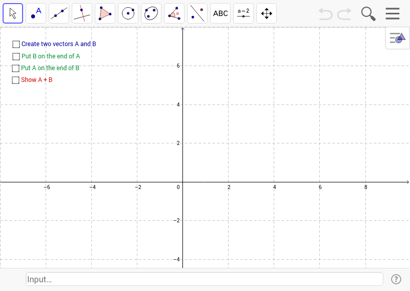
This example illustrates the geometric addition of two vectors using the Parallelogram Rule. It covers key concepts such as vector representation, the Parallelogram Law, and the geometric interpretation of vector addition. The construction leverages GeoGebra's Vector command, defining vectors u and v, and uses objects like points A, B, C and optional sliders a, b, c, d, e, f to dynamically build the parallelogram and display the resultant vector w. Ideal for high‑school geometry and vector courses, as well as introductory physics, it provides an interactive visual aid for understanding vector addition.
GeoGebra Commands & Parameters
Vector(A) → F_1Vector(B) → F_2Vector(A, A + B) → uVector(B, B + A) → vVector(C) → F_3Vector(C, C + A + B) → aVector(A + B, A + B + C) → b
AI Drawing Prompt Reference
Create a diagram illustrating vector addition using the parallelogram rule. Place two initial points on a coordinate plane, draw two vectors from the origin to these points, and use them as adjacent sides of a parallelogram. Complete the parallelogram and draw the diagonal from the origin as the resultant vector. Additionally, include a third vector starting from one vertex of the parallelogram, and draw its translated copy to show vector translation. Ensure all vectors have clear arrows, the grid is visible, and labels are included for clarity.
The prompt above was compiled from the original drawing commands and is for reference only.