
Geometric Addition of Integers on a Number Line via Translation
Loading the math board and drawing, please wait…
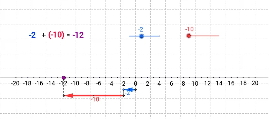
This example demonstrates how addition of integers can be visualized on the real number line by turning the algebraic operation into a geometric displacement. It centers on representing positive/negative integers as positions on a line and interpreting “add an integer” as shifting a point by a corresponding vector. Key math concepts include number-line representation, vectors as directed quantities, and translation as the geometric counterpart of addition, reinforced by auxiliary constructions (intersections and perpendicular lines). Construction-wise, it uses Line and Point to build the number line and anchor points, Segment and Midpoint to define and locate relevant segment features, Circle and OrthogonalLine together with Intersect to establish auxiliary constraints and compute key points, Vector to encode the displacement, and Translate to move from the start position to the resulting position that represents the integer sum. Suitable for middle and high school learners and for classroom demonstrations that aim to strengthen intuition behind integer arithmetic using dynamic geometry.
GeoGebra Commands & Parameters
Line(A, B) → aPoint(a) → CCircle(C, 2) → pOrthogonalLine(C, a) → dPoint(a) → DPoint(a) → EPoint(a) → FPoint(a) → GPoint(a) → HPoint(a) → IPoint(a) → JPoint(a) → KPoint(a) → LPoint(a) → MPoint(a) → NPoint(a) → OPoint(a) → PPoint(a) → QPoint(a) → RPoint(a) → SPoint(a) → TPoint(a) → UPoint(a) → VPoint(a) → WPoint(a) → YPoint(a) → ZPoint(a) → A_1Point(a) → B_1Point(a) → C_1Point(a) → D_1Point(a) → E_1Point(a) → F_1Point(a) → G_1Point(a) → H_1Intersect(p, d) → I_1, L_5OrthogonalLine(I_1, d) → eVector(I_1, L_1) → vOrthogonalLine(L_5, d) → hCircle(C, 4) → kIntersect(k, d, 1) → J_1OrthogonalLine(J_1, d) → fVector(J_1, K_1) → uVector(L_5, M_1) → wCircle(L_5, 1) → gIntersect(g, d, 1) → N_1OrthogonalLine(N_1, d) → iCircle(M_1, 1) → qIntersect(q, i) → O_1, P_1Translate(O_1, v) → Q_1Vector(O_1, Q_1) → zIntersect(k, d, 2) → R_1Circle(R_1, N_1) → rIntersect(r, d, 2) → S_1OrthogonalLine(S_1, d) → jVector(S_1, T_1) → lSegment(J_1, S_1) → mSegment(M_1, O_1) → tOrthogonalLine(K_1, a) → nIntersect(n, a) → U_1OrthogonalLine(L_1, a) → sOrthogonalLine(T_1, a) → a_1Intersect(s, a) → W_1Intersect(a_1, a) → Y_1Segment(K_1, U_1) → b_1Segment(T_1, Y_1) → c_1Segment(L_1, W_1) → d_1Segment(I_1, L_1) → b_2Segment(J_1, K_1) → e_1Segment(L_5, M_1) → f_1Segment(Q_1, O_1) → g_1Segment(T_1, S_1) → h_1Midpoint(J_1, K_1) → Z_1Midpoint(I_1, L_1) → A_2Midpoint(L_5, M_1) → B_2Midpoint(Q_1, O_1) → C_2Segment(Q_1, Y_1) → i_1Point(a) → V_1Point(a) → D_2Point(a) → E_2Point(a) → F_2Point(a) → G_2Point(a) → H_2Point(a) → I_2Point(a) → J_2Point(a) → K_2Point(a) → L_2
AI Drawing Prompt Reference
Draw a number line with point C as the origin and the right direction as positive. Mark points D to Z on the number line. Draw a circle centered at C with radius 2, intersecting the vertical line d at points I1 and L5. Draw a vector v starting from I1 in the direction of L1. Draw a circle centered at L5 with radius 4, intersecting the vertical line d at point J1, and draw a vector u starting from J1 in the direction of K1. Draw a circle centered at L5 with radius 1, intersecting the vertical line d at point N1, and draw a vector w starting from N1 in the direction of M1. Draw a circle centered at M1 with radius 1, intersecting the vertical line d at points O1 and P1.
The prompt above was compiled from the original drawing commands and is for reference only.