
GeoGebra demo: why a triangle’s angle sum may not be 180°
Loading the math board and drawing, please wait…
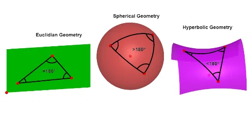
This example demonstrates that the sum of the interior angles of a “triangle” need not equal 180° when the geometry is defined on a non-Euclidean/curved metric space (commonly illustrated with spherical triangles). It visualizes how the angle sum depends on the underlying surface and the way the triangle’s sides are formed by arcs rather than straight segments. Key concepts include spherical (non-Euclidean) geometry, circular/spherical arcs, angle measurement at triangle vertices, and comparing the computed angle sum to 180°. Construction follows the GeoGebra workflow reflected in the command summary: it builds 3D objects and regions using Sphere and Surface, creates arc-based triangle boundaries via CircumcircleArc and CircleArc, defines vertices with Point and organizes the figure using Polygon and Line, and measures the interior angles using Angle (with auxiliary tools such as Midpoint and Centroid when needed for point placement). Suitable for advanced middle school, enrichment programs, and teaching/learning activities introducing the role of geometry axioms and metric assumptions in classical results.
GeoGebra Commands & Parameters
Sequence(CurveCartesian[x(O) + (f(t) * sin(s)), y(O) - t, z(O) + (f(t) * cos(s)), t, Min, Max], s, ((0.8 * π) * Rot / 24), ((1.5 * π) * Rot / 24), π / dx) → l1Line(O, yAxis) → gPoint(l1) → BPoint(l1) → CPoint(l1) → DSurface(x(O) + (f(t) * sin(s)), y(O) - t, z(O) + (f(t) * cos(s)), s, ((0.5 * π) * Rot / 24), ((1.5 * π) * Rot / 24), t, -2, 2) → aSphere(A, 2) → bPoint(l1) → EPoint(l1) → FPoint(l1) → GCircumcircleArc(B, E, C) → cCircumcircleArc(C, F, D) → dCircumcircleArc(B, G, D) → ePointIn(b) → HPointIn(b) → ICircleArc(A, H, I) → qPolygon(N, M, L, K) → q1, n, m, l, k_1PointIn(b) → JCircleArc(A, H, J) → pCircleArc(A, I, J) → rPointIn(q1) → PPointIn(q1) → QPointIn(q1) → RPolygon(P, Q, R) → t1, r_1, p_1, q_1Angle(Q, P, R) → αAngle(P, R, Q) → βAngle(R, Q, P) → γRay(A, H) → iPoint(q, 0.5 / q) → SPoint(p, 0.5 / p) → TPoint(r, 0.5 / r) → UPoint(r, 2.5 / r) → VCircleArc(H, S, T) → sPoint(q, 2 / q) → WCircleArc(I, U, W) → tPoint(p, 2 / p) → ZCircleArc(J, Z, V) → c_1Point(c, 0.5 / c) → A_1Point(c, 2.5 / c) → B_1Point(d, 0.5 / d) → C_1Point(d, 2 / d) → D_1Point(e, 0.5 / e) → E_1Point(e, 2.5 / e) → F_1CircleArc(B, E_1, A_1) → d_1CircleArc(C, C_1, B_1) → e_1CircleArc(D, D_1, F_1) → f_1Midpoint(n) → G_1Centroid(t1) → H_1Midpoint(H, J) → K_1Midpoint(I, J) → L_1Midpoint(L_1, K_1) → M_1Midpoint(H, I) → N_1Midpoint(N_1, M_1) → O_1Midpoint(O_1, M_1) → P_1Ray(A, P_1) → jIntersect(j, b) → Q_1,Midpoint(C, D) → R_1Midpoint(B, D) → S_1Midpoint(R_1, S_1) → U_1
AI Drawing Prompt Reference
Create a 3D spherical/curved-space scene with a triangle whose sides are circular arcs rather than straight segments. First draw a space curve on/around a sphere and pick multiple points on it to serve as vertices and auxiliary points. Use arc constructions defined by three points to generate three arc-like sides, forming an enclosed arc-based triangular region on the sphere. Add a few reference points within the sphere and on the arc boundaries to complete the arc contours. Finally, at the three triangle vertices measure the three interior angles corresponding to the ordered triples (Q,P,R), (P,R,Q), and (R,Q,P), intended for comparison with 180°.
The prompt above was compiled from the original drawing commands and is for reference only.