
General Reflection at an Air-Water Interface
Loading the math board and drawing, please wait…
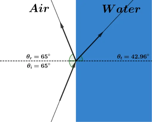
This example demonstrates the general reflection phenomenon at an air-water interface, illustrating the principles of reflection law, the relationship between incident and reflected angles, and vector and angle calculations. It utilizes GeoGebra commands/objects like Polygon, Ray, Vector, Segment, InteriorAngles, Angle, and Textfield for construction. Suitable for high school physics and mathematics courses to understand wave optics and geometric optics principles.
GeoGebra Commands & Parameters
Polygon(H, I, J, K) → c1, h_1, i, j, kRay(A, D) → fRay(A, B) → gRay(A, F) → hVector(A, F) → uVector(A, B) → vVector(D, A) → wSegment(C, A) → mSegment(A, E) → lInteriorAngles(c1) → α, β, γ, δAngle(l, h) → εAngle(B, A, C) → ζAngle(C, A, D) → ηTextfield(θ_i) → CasillaDeEntrada1
AI Drawing Prompt Reference
Draw a diagram illustrating general reflection at an air-water interface. Start with a quadrilateral representing the water surface. From a point on the interface, draw three rays: one incident ray, one reflected ray, and one normal direction. Use arrows to indicate the directions of the incident and reflected rays, and draw a vector from below the interface to the point to represent the normal. Add two auxiliary segments at the point for angle measurements. Label the interior angles of the quadrilateral, and show the incident angle, reflected angle, and the angle between the incident ray and the normal. Include a text input field for the incident angle value. The layout should clearly show that the incident angle equals the reflected angle.
The prompt above was compiled from the original drawing commands and is for reference only.