
Bearings with Wind via Vector and Trigonometry
Loading the math board and drawing, please wait…
In collections
Vectors
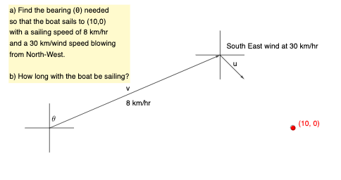
This example demonstrates how bearings (direction angles) change when wind is present, by visualizing the resulting heading/offset using geometric constructions. The key mathematical ideas are vector addition and decomposition to model wind plus intended travel, trigonometric functions to relate angles to right-triangle geometry, and the use of intersection points and segment constructs to read off the relevant bearing angles from the diagram. Construction-wise, it uses GeoGebra commands such as Vector to create the underlying vectors (e.g., u, v, and other direction components), Intersect to determine key crossing points that anchor the right-triangle/angle configuration, and Segment to build the directed edges used for angle measurement and comparison. Suitable for students learning trigonometry and vector-based modeling, from advanced high school through introductory college coursework, and for classroom activities focused on “bearing with wind” interpretation.
GeoGebra Commands & Parameters
Vector(F, E) → uIntersect(xAxis, yAxis) → GVector(G, F) → vSegment(A, B) → fSegment(C, D) → gPoint(yAxis) → HSegment(H, I) → hPoint(xAxis) → KSegment(J, K) → iPoint(xAxis) → L
AI Drawing Prompt Reference
Draw a coordinate plane with horizontal and vertical axes. Place a point on the vertical axis as a starting reference, and another point on the horizontal axis to form a right triangle. Construct three directed segments from a common origin: one representing the intended travel direction without wind, one representing the wind vector, and one representing the resultant actual heading. These segments should diverge to show angle differences. Additionally, mark points on both axes and connect them to the triangle vertices with segments to indicate bearing angles. The overall figure illustrates how wind alters the bearing via vector addition and trigonometric relationships.
The prompt above was compiled from the original drawing commands and is for reference only.