
Five-Ball Newton’s Cradle: Symmetric Collisions and Geometric Trajectories
Loading the math board and drawing, please wait…
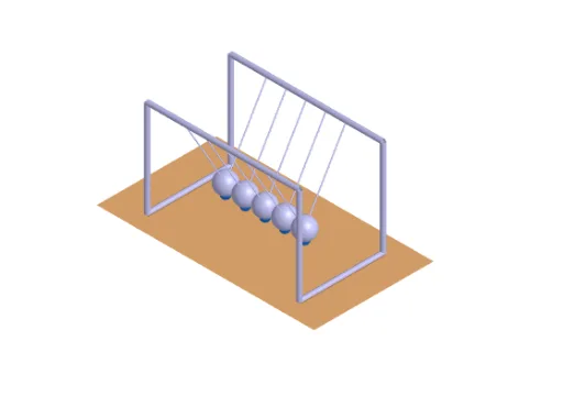
This example demonstrates the motion of a five-sphere Newton’s cradle, showing how identical free balls exchange momentum through repeated collisions. By adjusting initial pull settings (e.g., angle and length-related parameters), the construction reveals how symmetry and consistent geometric relationships shape the observed trajectories. Key mathematics includes circle/arc geometry, angle construction and measurement, correspondence of positions under symmetry-like updates, and parameterized control of motion via angular variables (such as θ and φ) to drive dynamic positions. In GeoGebra, the model is built using Line and Point for the pendulum lines and pivot-related points, Angle to define the pulling angle, Intersect to compute key geometric intersections, Polygon for outlines, and If for conditional updates of states. For the 3D presentation, Cylinder and Sphere render the physical components, while CircumcircleArc helps establish circular/arc structure. Dynamic object parameters and controllers (e.g., lengthController, widthController, heightController, pendulumRadius, trajectoryRadius, g) together with objects like pullPoint_i, restPosition, trajectoryCenter_i, and dynamicPosition_i generate and update each ball’s position and trajectory. Suitable for upper secondary through early university instruction on geometric constructions, parameterized animation, and mathematical visualization of physical-style systems.
GeoGebra Commands & Parameters
Line(basePoint, zAxis) → jPoint(j) → heightControllerLine(basePoint, yAxis) → gPoint(g) → widthControllerLine(basePoint, xAxis) → fPoint(f) → lengthControllerCircumcircleArc(trajectoryCenter_{3} + ((-pullRadius), 0, 0), trajectoryCenter_{3} + (0, 0, (-pullRadius)), trajectoryCenter_{3} + (pullRadius, 0, 0)) → e_2Point(e_2) → pullPoint_{3}Angle(pullPoint_{3}, trajectoryCenter_{3}, trajectoryCenter_{3} + restPosition, yAxis) → θ_{i}CircumcircleArc(trajectoryCenter_{4} + ((-pullRadius), 0, 0), trajectoryCenter_{4} + (0, 0, (-pullRadius)), trajectoryCenter_{4} + (pullRadius, 0, 0)) → r_2Point(r_2) → pullPoint_{4}Angle(pullPoint_{4}, trajectoryCenter_{4}, trajectoryCenter_{4} + restPosition, yAxis) → φ_{i}CircumcircleArc(trajectoryCenter_{2} + ((-pullRadius), 0, 0), trajectoryCenter_{2} + (0, 0, (-pullRadius)), trajectoryCenter_{2} + (pullRadius, 0, 0)) → d_2Point(d_2) → pullPoint_{2}CircumcircleArc(trajectoryCenter_{1} + ((-pullRadius), 0, 0), trajectoryCenter_{1} + (0, 0, (-pullRadius)), trajectoryCenter_{1} + (pullRadius, 0, 0)) → c_2Point(c_2) → pullPoint_{1}Angle(pullPoint_{1}, trajectoryCenter_{1}, trajectoryCenter_{1} + restPosition, yAxis) → γ_{i}CircumcircleArc(trajectoryCenter_{5} + ((-pullRadius), 0, 0), trajectoryCenter_{5} + (0, 0, (-pullRadius)), trajectoryCenter_{5} + (pullRadius, 0, 0)) → s_2Point(s_2) → pullPoint_{5}Angle(pullPoint_{5}, trajectoryCenter_{5}, trajectoryCenter_{5} + restPosition, yAxis) → ω_{i}Angle(pullPoint_{2}, trajectoryCenter_{2}, trajectoryCenter_{2} + restPosition, yAxis) → δ_{i}Line(widthController, f) → hLine(lengthController, g) → iIntersect(i, h) → DPolygon(basePoint, lengthController, D, widthController) → q1, a, b, d, cCylinder(J, K, cylinderRadius) → e, k, p, lCylinder(M, L, cylinderRadius) → m, q, r, nCylinder(H, J, cylinderRadius) → o, s, t, uCylinder(F, K, cylinderRadius) → v, c_1, d_1, wCylinder(E, L, cylinderRadius) → a_1, e_1, f_1, b_1Cylinder(G, M, cylinderRadius) → g_1, g_2, g_3, g_4Cylinder(F, E, cylinderRadius) → h_1, k_1, p_1, i_1Cylinder(G, H, cylinderRadius) → j_1, q_1, r_1, l_1If(time ≤ π / 2, trajectoryCenter_{1} + dynamicPosition_{1}, trajectoryCenter_{1} + dynamicPosition_{5}) → sphereCenter_{1}Segment(U, sphereCenter_{1}) → f_2Segment(sphereCenter_{1}, V) → h_2If(time ≤ π / 2, trajectoryCenter_{2} + dynamicPosition_{2}, trajectoryCenter_{2} + dynamicPosition_{4}) → sphereCenter_{2}Segment(Z, sphereCenter_{2}) → i_2Segment(sphereCenter_{2}, W) → j_2Segment(sphereCenter_{3}, A_1) → k_2Segment(sphereCenter_{3}, B_1) → l_2If(time ≤ π / 2, trajectoryCenter_{4} + dynamicPosition_{4}, trajectoryCenter_{4} + dynamicPosition_{2}) → sphereCenter_{4}Segment(D_1, sphereCenter_{4}) → m_2Segment(sphereCenter_{4}, C_1) → n_2If(time ≤ π / 2, trajectoryCenter_{5} + dynamicPosition_{5}, trajectoryCenter_{5} + dynamicPosition_{1}) → sphereCenter_{5}Segment(E_1, sphereCenter_{5}) → p_2Segment(sphereCenter_{5}, F_1) → q_2Sphere(sphereCenter_{1}, sphereRadius) → m_1Sphere(sphereCenter_{2}, sphereRadius) → n_1Sphere(sphereCenter_{3}, sphereRadius) → o_1Sphere(sphereCenter_{4}, sphereRadius) → s_1Sphere(sphereCenter_{5}, sphereRadius) → t_1
AI Drawing Prompt Reference
Draw a diagram of a five-ball Newton's cradle showing symmetric collisions and geometric trajectories. The diagram should include five ball bodies connected to symmetric trajectory centers, with paths illustrating post-collision motion. Angles and parameters should be reflected in the layout. Construction order: first establish trajectory centers, then draw the balls, and finally connect them to the centers. Maintain symmetry to highlight geometric relationships and dynamic trajectories.
The prompt above was compiled from the original drawing commands and is for reference only.