
Electromechanical Rotation
Loading the math board and drawing, please wait…
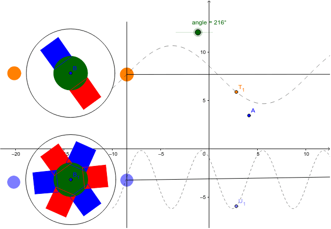
This example demonstrates the concept of electromechanical rotation. It involves core mathematical concepts such as Rotation, Indefinite Integral, Random Variables, Geometric Mean, Differential Calculus, and Congruence. The construction utilizes GeoGebra commands like Circle, Polygon, Rotate, Function, and Segment. It is suitable for high school students and engineers studying electromechanical systems.
GeoGebra Commands & Parameters
Circle(B, C) → ePolygon(D, E, F, G) → poly1, d, e_1, f, gPolygon(D_1, E_1, F_1, G_1) → poly1_1, d_1, e_2, f_1, g_1Circle(B_1, C_1) → e_3Polygon(D_2, E_2, F_2, G_2) → poly1_2, d_2, e_4, f_2, g_2Polygon(D_3, E_3, F_3, G_3) → poly1_3, d_3, e_5, f_3, g_3Rotate(D_2, -2.0933333333333333, B_1) → HRotate(E_2, -2.0933333333333333, B_1) → IRotate(F_2, -2.0933333333333333, B_1) → JRotate(G_2, -2.0933333333333333, B_1) → KPolygon(H, I, J, K) → poly2, h, i, j, kRotate(D_2, 2.0933333333333333, B_1) → LRotate(E_2, 2.0933333333333333, B_1) → MRotate(F_2, 2.0933333333333333, B_1) → NRotate(G_2, 2.0933333333333333, B_1) → OPolygon(L, M, N, O) → poly3, l, m, n, oRotate(D_3, 2.0933333333333333, B_1) → PRotate(E_3, 2.0933333333333333, B_1) → QRotate(F_3, 2.0933333333333333, B_1) → RRotate(G_3, 2.0933333333333333, B_1) → SPolygon(P, Q, R, S) → poly4, p, q, r, sRotate(D_3, -2.0933333333333333, B_1) → TRotate(E_3, -2.0933333333333333, B_1) → URotate(F_3, -2.0933333333333333, B_1) → VRotate(G_3, -2.0933333333333333, B_1) → WPolygon(T, U, V, W) → poly5, t, u, v, wRotate(D_2, angle, B_1) → ZRotate(E_2, angle, B_1) → A_1Rotate(F_2, angle, B_1) → H_1Rotate(G_2, angle, B_1) → I_1Polygon(Z, A_1, H_1, I_1) → poly6, z, a_1, h_1, i_1Rotate(T, angle, B_1) → T'Rotate(U, angle, B_1) → U'Rotate(V, angle, B_1) → V'Rotate(W, angle, B_1) → W'Polygon(T', U', V', W') → poly5', t', u', v', w'Rotate(L, angle, B_1) → L'Rotate(M, angle, B_1) → M'Rotate(N, angle, B_1) → N'Rotate(O, angle, B_1) → O'Polygon(L', M', N', O') → poly3', l', m', n', o'Rotate(D_3, angle, B_1) → J_1Rotate(E_3, angle, B_1) → K_1Rotate(F_3, angle, B_1) → L_1Rotate(G_3, angle, B_1) → M_1Polygon(J_1, K_1, L_1, M_1) → poly7, j_1, k_1, l_1, m_1Rotate(H, angle, B_1) → H'Rotate(I, angle, B_1) → I'Rotate(J, angle, B_1) → J'Rotate(K, angle, B_1) → K'Polygon(H', I', J', K') → poly2', h', i', j', k'Rotate(P, angle, B_1) → P'Rotate(Q, angle, B_1) → Q'Rotate(R, angle, B_1) → R'Rotate(S, angle, B_1) → S'Polygon(P', Q', R', S') → poly4', p', q', r', s'Rotate(D, angle, B) → D'Rotate(E, angle, B) → E'Rotate(F, angle, B) → F'Rotate(G, angle, B) → G'Polygon(D', E', F', G') → poly1', d', e', f', g'Rotate(D_1, angle, B) → N_1Rotate(E_1, angle, B) → O_1Rotate(F_1, angle, B) → P_1Rotate(G_1, angle, B) → Q_1Polygon(N_1, O_1, P_1, Q_1) → poly8, n_1, o_1, p_1, q_1Circle(R_1, S_1) → cCircle(R_2, S_2) → c_1Function((3 * sin((x - 10.47) / 3 + 0.05)) + 7.68, -10, 15) → r_1Function((3 * sin(x + 2.31)) - 3.16, -10, 15) → s_1Circle(B, V_1) → t_1Circle(B_1, W_1) → c_2Segment(B_2, C_2) → b_1Segment(R_1, Z_1) → aSegment(R_2, A_2) → bCircle(R_3, S_3) → c_3Circle(R_4, S_4) → c_4
AI Drawing Prompt Reference
Create a diagram illustrating electromechanical rotation with multiple circles and quadrilaterals, showing rotational relationships through geometric transformations. Start by drawing two circles, then create several quadrilaterals and rotate them around a central point to form a symmetrical rotational structure. Some quadrilaterals should be rotated around the circumference of a circle while maintaining geometric relationships. The final image should display rotational and symmetrical effects, suitable for educational purposes.
The prompt above was compiled from the original drawing commands and is for reference only.