
Dyme - 2.5 (with numbers)
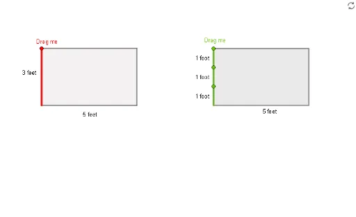
Loading the math board and drawing, please wait…
This example demonstrates the geometric construction of Dyme - 2.5 (with numbers). Key mathematical concepts include area, numbers, logarithm, standard deviation, sphere, arithmetic mean, and cube. Using GeoGebra commands such as Point, OrthogonalLine, Intersect, Line, Segment, and Polygon, complex geometric shapes are constructed. Suitable for high school mathematics education and learning.
GeoGebra Commands & Parameters
Point(xAxis) → AOrthogonalLine(B, yAxis) → fOrthogonalLine(A, xAxis) → gIntersect(f, yAxis) → CIntersect(xAxis, yAxis) → DLine(C, D) → hSegment(A, D) → iSegment(B, C) → jSegment(B, A) → kSegment(C, D) → lIntersect(j, k) → EIntersect(i, k) → FIntersect(i, l) → GIntersect(j, l) → HPolygon(E, F, G, H) → q1, e, f_1, g_1, h_1Intersect(i, k) → IOrthogonalLine(I, j) → mIntersect(m, j) → JPoint(j) → KOrthogonalLine(K, i) → nIntersect(n, i) → LSegment(K, L) → pOrthogonalLine(N, xAxis) → qOrthogonalLine(N, yAxis) → rPoint(r) → MOrthogonalLine(M, xAxis) → sIntersect(s, xAxis) → OOrthogonalLine(O, q) → tIntersect(q, t) → PSegment(N, M) → aSegment(M, O) → bSegment(O, P) → cSegment(P, N) → dPolygon(N, P, O, M) → q2, n_1, p_1, o, m_1Intersect(c, d) → QPoint(d) → ROrthogonalLine(Q, xAxis) → i_1OrthogonalLine(R, b) → j_1Intersect(b, c) → SOrthogonalLine(S, j_1) → k_1Point(d) → VOrthogonalLine(V, xAxis) → r_1Point(d) → WOrthogonalLine(W, b) → s_1Intersect(b, o) → ZIntersect(s_1, b) → A_1OrthogonalLine(A_1, xAxis) → t_1Intersect(t_1, b) → B_1Intersect(t_1, b) → C_1Intersect(t_1, b) → D_1Intersect(t_1, b) → E_1Intersect(t_1, b) → F_1Intersect(t_1, b) → G_1Intersect(t_1, b) → H_1Point(q2) → I_1OrthogonalLine(I_1, d) → a_1Polygon(W, V, I_1, A_1) → q3, w, v, b_1, c_1Point(c_1) → J_1OrthogonalLine(J_1, a_1) → d_1Intersect(a_1, d_1) → K_1Segment(J_1, K_1) → e_1Intersect(a, d) → L_1OrthogonalLine(L_1, xAxis) → f_2Intersect(f_2, d) → M_1Point(d) → N_1OrthogonalLine(N_1, b) → g_2Intersect(b, o) → O_1Intersect(b, o) → P_1Point(b) → Q_1OrthogonalLine(Q_1, xAxis) → h_2Point(h_2) → R_1OrthogonalLine(R_1, yAxis) → i_2Polygon(L_1, N_1, Q_1, R_1) → q4, j_2, k_2, l_2, m_2Point(a) → S_1OrthogonalLine(S_1, xAxis) → n_2Intersect(g_2, n_2) → T_1Segment(S_1, T_1) → p_2Point(d) → U_1Intersect(c, d) → V_1Point(c) → W_1Point(b) → Z_1Polygon(U_1, V_1, W_1, Z_1) → q5, u_1, v_1, w_1, z_1Point(z_1) → TOrthogonalLine(T, xAxis) → l_1Intersect(l_1, c) → USegment(T, U) → q_1Intersect(a, d) → A_2Intersect(c, d) → B_2Intersect(b, c) → C_2Intersect(a, b) → D_2Polygon(A_2, B_2, C_2, D_2) → q6, a_2, b_2, c_2, d_2
AI Drawing Prompt Reference
Draw a complex geometric figure consisting of multiple squares and rectangles. Start by creating point A on the x-axis, then create a vertical line f through point B and the y-axis, and create a vertical line g through point A and the x-axis. Find the intersection of f and the y-axis (point C), and the intersection of the x-axis and y-axis (point D). Then create line h through C and D, and line segments i through A and D, j through B and C, k through B and A, and l through C and D. Next, find the intersection of j and k (point E), i and k (point F), i and l (point G), and j and l (point H). Create quadrilateral q1 through points E, F, G, and H. Continue by creating line m through I and j, finding the intersection of m and j (point J), creating point K through j, creating a vertical line n through K and i, finding the intersection of n and i (point L), creating line segment p through K and L. Then create vertical line q through N and the x-axis, vertical line r through N and the y-axis, finding the intersection of r and the x-axis (point M), creating a vertical line s through M and the x-axis, finding the intersection of s and the x-axis (point O), creating a vertical line t through O and q, finding the intersection of t and q (point P), creating line segment a through N and M, line segment b through M and O, line segment c through O and P, and line segment d through P and N. Finally, create quadrilateral q2 through points N, P, O, and M.
The prompt above was compiled from the original drawing commands and is for reference only.