
Drawing Cross Sections of a Prism
Loading the math board and drawing, please wait…
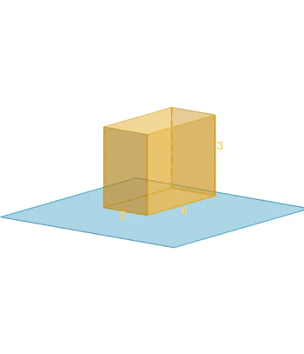
This example demonstrates how to draw cross sections of a prism using GeoGebra. Key mathematical concepts include solid geometry and geometric construction. Commands used include Polygon, PointIn, Translate, Rotate, Prism, Plane, IntersectPath, and OrthogonalLine. Suitable for high school geometry students and educators.
GeoGebra Commands & Parameters
Polygon(B + (-2, -2), B + (2, -2), B + (2, 2), B + (-2, 2)) → poly3, e, f, g, iPointIn(poly3) → CTranslate((0, 0, 0), Vector[B, C]) → APolygon(A + (-4, -4), A + (4, -4), A + (4, 4), A + (-4, 4)) → poly1, a, b, c, dRotate(Rotate[Translate[poly1, Vector[A, A + (0, 0, h)]], (90° * s), A + (0, 0, h), yAxis], (90° * t), A, zAxis) → poly2Prism(Polygon[(1, 2, 0), (1, -2, 0), (-1, -2, 0), (-1, 2, 0)], 3) → m, M, edge1, edge2, edge3, edge4, edge5, edge6, edge7, edge8, N, Q, R, face1, face2, face3, face4, face5Rotate(D, 120°, (0, 0, 0)) → EPolygon(D, E, 3, xOyPlane) → poly4, j, k, l, FPointIn(poly2) → GPointIn(poly2) → HPointIn(poly2) → IPlane(G, I, H) → nIntersectPath(n, m) → poly6, poly5, r, a_1, b_1, c_1, K, L_1, O, P, J, L, p, qRotate(m, 0, zAxis) → m'Rotate(m, 0, zAxis) → m'_1OrthogonalLine(A, n) → d_1
AI Drawing Prompt Reference
Draw a prism and show how to generate its cross sections through rotation and transformation. Start by sketching a rectangular base, then extend it vertically to form the prism. Next, select a point on the base and rotate the rectangle around this point to create an inclined rectangle. Finally, intersect the prism with two parallel planes to obtain a cross-sectional polygon, labeling key points and lines.
The prompt above was compiled from the original drawing commands and is for reference only.