
Customizing the 3D Graphics View: Using the Style Bar for Solid Geometry
Loading the math board and drawing, please wait…
In collections
Learn GeoGebra Classic
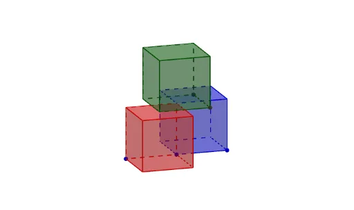
This example demonstrates how to customize the 3D Graphics View in GeoGebra using the Style Bar, using a cube with internal constructions as a visual case. It focuses on solid geometry concepts including cubes, midpoints, faces, and edges, while also touching on the Pythagorean theorem and trigonometric functions in a 3D context. The construction involves using the Point command to create key points A, B, C, D, etc., the Cube command to build the cube, and the Midpoint command to generate midpoints E, F, G, H, etc. Multiple faces (such as faceABDE, faceAEIF) and edges (edgeAE, edgeAB) are defined to form a complete cube framework with internal auxiliary structures. This example is suitable for middle and high school mathematics teachers to use in solid geometry lessons, helping students understand spatial relationships in 3D, and for students to explore GeoGebra's 3D Style Bar features to enhance their skills in 3D visualization.
GeoGebra Commands & Parameters
Point(Circle[B, Distance[A, B], Segment[A, B]]) → DCube(A, B, D) → a, E, faceDEIH, faceFGHI, edgeAE, edgeAB, edgeBD, edgeDE, edgeAF, edgeEI, edgeFI, edgeFG, F, edgeBG, edgeGH, edgeDH, edgeHI, G, H, I, faceABDE, faceAEIF, faceABGF, faceBDHGPoint(Circle[C, Distance[A, C], Segment[A, C]]) → JCube(A, C, J) → b, K, faceJKON, faceLMNO, edgeAK, edgeAC, edgeCJ, edgeJK, edgeAL, edgeKO, edgeLO, edgeLM, L, edgeCM, edgeMN, edgeJN, edgeNO, M, N, O, faceACJK, faceAKOL, faceACML, faceCJNMMidpoint(G, O) → PMidpoint(G, I) → QPoint(Circle[Q, Distance[P, Q], Segment[P, Q]]) → RCube(P, Q, R) → c, S, faceRSWV, faceTUVW, edgePS, edgePQ, edgeQR, edgeRS, edgePT, edgeSW, edgeTW, edgeTU, T, edgeQU, edgeUV, edgeRV, edgeVW, U, V, W, facePQRS, facePSWT, facePQUT, faceQRVU
AI Drawing Prompt Reference
Draw a cube with internal constructions. Start by creating a cube and mark several key points on its faces. Connect these points to form multiple faces and edges. Then, find midpoints of some points and construct another smaller cube using these midpoints and points. The final image should display the internal structure of the cube, including multiple faces, edges, midpoints, and the smaller auxiliary cube, highlighting spatial relationships and internal constructions.
The prompt above was compiled from the original drawing commands and is for reference only.