
Comparing Rotation Directions: Clockwise vs Counterclockwise
Loading the math board and drawing, please wait…
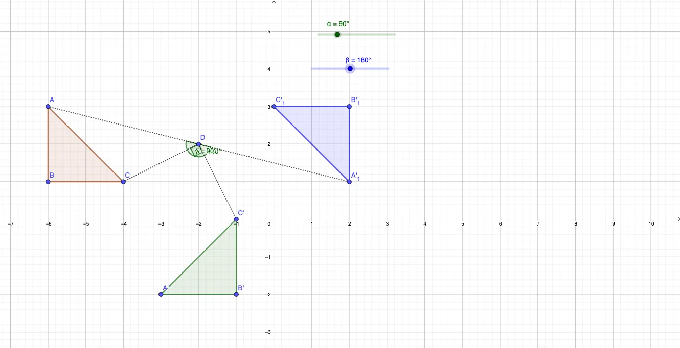
This GeoGebra example demonstrates how rotating the same geometric configuration in opposite directions (clockwise vs counterclockwise) changes the angle measurements and the resulting positions of key points and edges. It focuses on fundamental ideas of geometric transformation—especially rotation in the plane—and the directional meaning of angles. The construction uses Polygon to create the base polygonal shape, Rotate to generate its rotated counterparts for different angle parameters, Segment to display the significant connecting edges, and Angle to measure and visualize the defining rotation angles (e.g., α and β, together with their rotated versions). Multiple labeled objects and parameters (original points such as A, B, C and corresponding rotated points A', B', C', plus auxiliary variables like t, c, a, b) are used to synchronize the comparison and to make the difference between rotation directions immediately observable through the dynamic setup. Suitable for school-level geometry transformation lessons, interactive demonstrations, and exploratory learning about angle direction and rotation mapping.
GeoGebra Commands & Parameters
Polygon(A, B, C) → t1, c, a, bRotate(A, α, D) → A'Rotate(B, α, D) → B'Rotate(C, α, D) → C'Polygon(A', B', C') → t1', c', a', b'Rotate(A, (-β), D) → A'_1Rotate(B, (-β), D) → B'_1Rotate(C, (-β), D) → C'_1Polygon(A'_1, B'_1, C'_1) → t1'_1, c'_1, a'_1, b'_1Segment(C, D) → fSegment(D, C'_1) → gSegment(A, D) → hSegment(D, A'_1) → iAngle(A, D, A'_1) → δSegment(B, D) → jSegment(D, A) → kSegment(D, B'_1) → lSegment(A, D) → mAngle(C, D, C') → γSegment(D, C') → n
AI Drawing Prompt Reference
Draw a geometric figure comparing clockwise and counterclockwise rotations. The figure should include an original triangle ABC, and two rotated triangles A'B'C' and A'_1B'_1C'_1, representing clockwise and counterclockwise rotations respectively. Also include line segments connecting point D to various points, and lines from original points to D and rotated points to D. Key objects include original points A, B, C, rotated points A', B', C', and A'_1, B'_1, C'_1, along with connecting line segments and angles. The construction order should be: first draw the original triangle ABC, then generate the two rotated triangles using clockwise and counterclockwise rotations, then draw line segments connecting point D to various points, and finally label key angles and line segments.
The prompt above was compiled from the original drawing commands and is for reference only.