
CAD with GeoGebra for STEM - Design a Glass (Solid of Revolution)
Loading the math board and drawing, please wait…
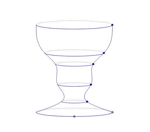
This GeoGebra applet demonstrates a CAD-style workflow for designing a glass by defining six free points that determine the profile of a solid of revolution about the y-axis. It integrates the Graphic, Algebra, and Spreadsheet views to support parametric modeling. Core mathematical concepts include solids of revolution, symmetry, coordinate geometry, and geometric transformations. The construction uses commands such as Point, Intersect, Line, Mirror, Sort, Element, Locus, Rotate, Segment, Dilate, Ellipse, OrthogonalLine, and Midpoint to build the profile, mirror it, generate the locus, and rotate it into a 3D surface. This example is ideal for high school to early college STEM courses, helping students connect algebra, geometry, and engineering design while developing spatial reasoning and parametric thinking skills.
GeoGebra Commands & Parameters
Point(xAxis) → FIntersect(xAxis, yAxis) → GLine(H, G) → aMirror(A, a) → A'Mirror(B, a) → B'Mirror(C, a) → C'Mirror(D, a) → D'Mirror(E, a) → E'Mirror(F, a) → F'Sort(prof) → prof2Element(s, 1, 1) → I3Element(s, 2, 1) → I4Element(s, 3, 1) → I5Element(s, 4, 1) → I6Mirror(O, a) → O'Locus(O', t) → loc1Mirror(O', yAxis) → O''Locus(O'', t) → loc2Mirror(L, a) → L'Mirror(L', yAxis) → L''Locus(L', t) → loc3Locus(L'', t) → loc4Mirror(K, a) → K'Mirror(K', yAxis) → K''Locus(K', t) → loc5Locus(K'', t) → loc6Mirror(J, a) → J'Mirror(J', yAxis) → J''Mirror(I, a) → I'Mirror(I', yAxis) → I''Locus(J', t) → loc7Locus(I', t) → loc8Locus(J'', t) → loc9Locus(I'', t) → loc10Rotate(F, 270*°, G) → F'_1Segment(G, F'_1) → aaPoint(aa) → PSegment(G, F) → cSegment(G, P) → bbDilate(F, ee, G) → F'_2Mirror(F'_2, G) → QEllipse(Q, F'_2, F) → dPoint(xAxis) → ROrthogonalLine(R, xAxis) → bIntersect(d, b, 1) → SLocus(S, R) → loc11Mirror(E, yAxis) → E'_1Mirror(D, yAxis) → D'_1Mirror(C, yAxis) → C'_1Mirror(B, yAxis) → B'_1Mirror(A, yAxis) → A'_1Midpoint(E'_1, E) → TMidpoint(D'_1, D) → UMidpoint(C'_1, C) → VMidpoint(B'_1, B) → WMidpoint(A'_1, A) → ZDilate(E, ee, T) → E'_2Dilate(D, ee, U) → D'_2Dilate(C, ee, V) → C'_2Dilate(B, ee, W) → B'_2Dilate(A, ee, Z) → A'_2Mirror(A'_2, Z) → A_1Mirror(B'_2, W) → B_1Mirror(C'_2, V) → C_1Mirror(E'_2, T) → D_1Ellipse(D_1, E'_2, E) → eEllipse(C_1, C'_2, C) → fEllipse(B_1, B'_2, B) → gEllipse(A_1, A'_2, A) → hMirror(D'_2, U) → E_1Ellipse(E_1, D'_2, D) → kSegment(A'_1, A) → iSegment(B'_1, B) → jSegment(C'_1, C) → lSegment(D'_1, D) → mSegment(E'_1, E) → nPoint(i) → F_1Point(j) → G_1Point(l) → H_1Point(m) → I_1Point(n) → J_1OrthogonalLine(F_1, i) → pIntersect(h, p, 1) → K_1Locus(K_1, F_1) → loc12OrthogonalLine(G_1, j) → qIntersect(g, q, 1) → L_1Locus(L_1, G_1) → loc13OrthogonalLine(J_1, n) → rIntersect(e, r, 1) → M_1Locus(M_1, J_1) → loc14OrthogonalLine(H_1, l) → a_1OrthogonalLine(I_1, m) → b_1Intersect(f, a_1, 1) → N_1Intersect(k, b_1, 1) → O_1Locus(N_1, H_1) → loc15Locus(O_1, I_1) → loc16
AI Drawing Prompt Reference
Draw a 3D glass formed by revolving a profile around the y-axis. Start with six free points on the coordinate plane defining one side of the glass profile. Mirror these points across a slanted line through the origin to create the symmetric other side. Connect all points in order to form a smooth outline. Revolve this outline around the y-axis to generate the solid surface. Add an elliptical base at the bottom, and use a vertical line perpendicular to the x-axis to intersect the ellipse, marking the base edge. Finally, mirror key profile points across the y-axis to ensure full symmetry, completing the glass shape.
The prompt above was compiled from the original drawing commands and is for reference only.